
Welcome to part 15 of the VCF-9.1 home lab series. The previous post in this series discussed implementing Distributed Transit Gateway (DTGW) and demonstrated how NSX VPCs used DTGW for network connectivity. This post will dive deep into inspecting the ingress and egress packet flow.
If you are not following along, I encourage you to read the earlier parts of this series from the links below:
3: VCF 9.1 Pre-Deployment Planning
4: Setting up VCF 9.1 Offline Depot
5: VCF 9.1 Deploy Management Domain
6: Configure Management Domain Network Connectivity
8: Enable Avi on Workload Domain
9: Deploy Supervisor in Workload Domain
11: VCFA Provider Management Configuration
12: Deploy VCF Operations for Logs
13: VNA Cluster for Distributed Connectivity
14: Distributed Transit Gateway for VPCs
Before diving into the lab, let’s do a quick recap of DTGW and the VNA cluster.
VCF 9.0 introduced the Distributed Transit Gateway—a way to route VPC traffic straight off the ESXi host transport nodes, with no NSX Edge VM in the path. The catch was that DTGW could only do stateless distributed routing. The moment a workload needed NAT, load balancing, or any other stateful service, you were pushed back to a Centralized Transit Gateway sitting behind an edge cluster.
VCF 9.1 closes that gap with the Virtual Network Appliance (VNA)—a purpose-built appliance cluster that plugs stateful services into the DTGW data path without reintroducing a full edge/tier-0 topology. The result is a hybrid model: routing stays distributed and host-local, while the VNA nodes process stateful services (NAT/LB/DNS).
Before starting to trace the packets, it is important to understand the building blocks of this setup.
| Component | Role |
| VPC Distributed Router (DR) | Kernel-space datapath instantiated on every ESXi transport node. Handles stateless routing for the VPC’s private subnets. |
| VPC Service Router (SR) | Runs inside the VNA node as a per-tenant VRF/namespace. Owns the gateway firewall, NAT rule table, connection-tracking state, and (for ingress) the proxy-ARP binding for public VIPs. |
| Distributed Transit Gateway | The distributed uplink construct that connects a VPC (via its DR) to an external VLAN |
| VNA Cluster | A purpose-built appliance that hosts the VPC Service Router context for a tenant. This is where stateful processing happens. |
| Geneve / TEP | The overlay encapsulation and tunnel endpoints used to move a packet between a compute host and the VNA host and back. |
| External Uplink | The VLAN-backed segment where the DTGW hands packets to the physical ToR fabric. |
VPC + DTGW + VNA Architecture
When a VPC uses the VNA-backed distributed transit gateway, the DR component lives on every ESXi host, and the SR component is created on the VNA node.
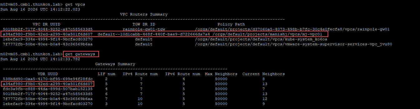

The VPC SR has an interface of type SVC_LINK that maintains the FW policies of the VPC gateway. Any stateful traffic is processed at this interface (similar to a VM vNIC in a DFW scenario)

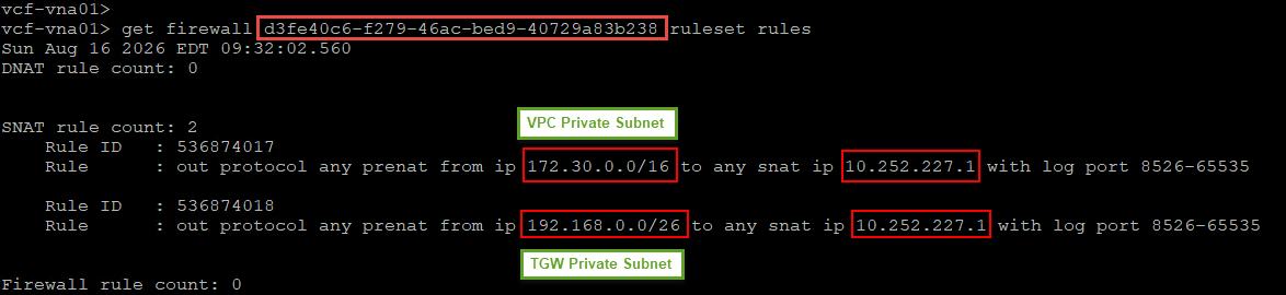
The firewall rules can be viewed against this interface
Now that we have a basic understanding of the architecture, let’s review the network setup. In my lab, the following networks are used in the DTGW setup.
| Network Type | VLAN/CIDR |
| Distributed External Connection | 10.252.227.254/24 (VL 227) |
| External IP Block | 10.252.227.0/24 |
| VPC Pvt Transit Gateway | 192.168.0.0/23 |
| VPC Private Subnet | 172.30.0.0/16 |
| VPC Public Subnet | 10.252.227.33/27 |
And this is how the lab topology looks.

Test Cases
From the VPC public subnet, initiate a ping to the following endpoints:
- google.com (for internet connectivity check)
- 10.252.80.1 (an IP on the infrastructure VLAN)
- 172.30.0.2 (A VM connected to the VPC’s private subnet)
From the VPC private subnet, initiate a ping to the following endpoints:
- google.com (for internet connectivity check)
- 10.252.80.1 (an IP on the infrastructure VLAN)
- 10.252.227.34 (A VM connected to the VPC’s public subnet)
The ping test summary from the public/private subnet is shown below


Egress Packet Walk (South –> North)
Egress from VM on Public Subnet
When communicating with an external endpoint located north of the Transit Gateway, workloads deployed on public subnets do not require Source Network Address Translation, even though auto SNAT is enabled for the VPC. These communications preserve the source IP address throughout the transmission path, allowing the external endpoint to receive and respond directly to the originating workload’s actual address.

For any packet outbound to the internet/physical infrastructure, the following sequence of events happens:
Step 1: The VM connected to the public subnet sends a packet to the destination (google.com). Since the path to the destination is unknown, the VM sends the packet to its default gateway (10.252.227.33), which is the LIF IP on the VPC Distributed Router (running on the ESXi host)

Step 2: The packet traverses the segment “mj-pub-net01” and is intercepted by the VPC Distributed Router (DR) context.
Step 3: The VPC DR, upon receiving the packet, checks its forwarding table to make a routing decision.
Step 4: Since a route to the destination doesn’t exist in the forwarding table, the VPC DR forwards the packet to the transit gateway via the transit link.

Step 5: The transit gateway receives the packet. Since no stateful services are needed, the transit gateway forwards the packet to its default gateway over the external uplink (VLAN-backed).

Step 6: The packet traverses the VLAN uplink and reaches the physical infrastructure, where the northbound router delivers it to the destination.
The above packet flow can be visualized by using the traceflow utility in the NSX UI.

Egress from VM on Private Subnet
When communicating with an external endpoint located north of the Transit Gateway, traffic originating from workloads on Private-VPC or Private-TGW subnets matches the Auto SNAT rule when present, unless a higher-priority rule has been configured on either the VPC Gateway or the Transit Gateway.

When “Default Outbound NAT” is enabled in the VPC profile, the system creates 2 NAT rules: one for the VPC private network and one for the Transit Gateway private subnet. Both networks use the same NAT IP for the outbound connection.

Although the SNAT IP address is identical for both rules, the system prevents source port conflicts by performing Port Address Translation (PAT) across non-overlapping port ranges—with the VPC Gateway and Transit Gateway each utilizing distinct port segments for their respective translations.
The NAT’d traffic first hits the VNA cluster for processing before egressing to the physical network.
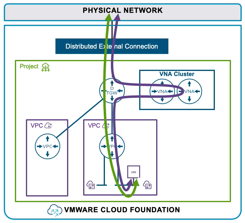
For any packet outbound to the internet/physical infrastructure, the following sequence of events happens:
Step 1: The VM connected to the private subnet sends a packet to the destination (10.252.80.1). Since the path to the destination is unknown, the VM sends the packet to its default gateway (172.30.0.1), which is the LIF IP on the VPC DR (running on the ESXi host).
Step 2: The packet traverses the segment “mj-pvt-net01” and is intercepted by the VPC Distributed Router (DR) context.
Step 3: The VPC DR, upon receiving the packet, inspects it and identifies that stateful service (NAT) is needed.
Step 4: The DR component checks its forwarding table to identify the next hop. The packet is then sent over the services subnet to the VNA node.

Step 5: Before the packet can be sent to the VNA node, the ESXi host encapsulates the packet into a GENEVE payload and sends it over the ESXi TEP network.
Step 6: The packet is received by the ESXi host where the VNA node is running.
Step 7: The packet is sent to the VNA node over the physical network.
Step 8: The encapsulated packet (Geneve payload) is received by the active VNA node at its physical network interface boundary.
Step 9: The packet is decapsulated and forwarded to the Edge Host Switch.
Step 10: The decapsulated packet is received by the VPC’s Service Router instance running on the VNA node.
Step 11: The packet is forwarded to the SVC_LINK interface for examination.
Step 12: The packet is then handed over to the NAT translation processing engine.
Step 13: The NAT engine registers a new flow entry in the connection tracking table, overwrites the private source address (172.30.0.2) with the assigned public IP pool, and calculates the new IP header checksum.
Step 14: The translated packet is routed out through the VPC Service Router.
Step 15: The modified packet loops back through the internal Edge Host Switch for encapsulation.
Step 16: The VNA node encapsulates the packet and transmits it back onto the physical fabric transit network.
Step 17: The ESXi host receives the post-NAT packet from the VNA node over the physical network.
Step 18: The packet is sent from the host to the VPC gateway over the VPC’s service interface.
Step 19: The VPC gateway receives the packet. It checks its forwarding table; since a route to the destination doesn’t exist, it sends the packet to its default gateway (100.64.0.0), which is the uplink interface (router link) on the transit gateway.

Step 20: The incoming packet is received by the DTGW.
Step 21: The transit gateway checks its forwarding table to make a routing decision. Since a direct route to the destination doesn’t exist, it sends the packet to its default gateway over its external uplink (VLAN-backed)
Step 22: The packet is delivered to the Top-of-Rack (ToR) switch, from where it reaches the destination.
The above packet flow can be visualized by using the traceflow utility in the NSX UI.

When a packet is sent from the private subnet to the external VM, the firewallpkt.log file can be examined in real time to see the NAT in action.

Ingress Packet Walk (North –> South)
External VM to VM on VPC Private Subnet
For an external VM to communicate with a VM on a VPC’s private subnet, connectivity must be established first. The easiest way is to create a DNAT rule for the private subnet VM. This is a 1:1 NAT, and the external IP of the private VM is the destination for the external VM.
Create a new DNAT rule in the VPC. The internal IP must be entered in the Translated IP field. For the external IP, click Request IP.
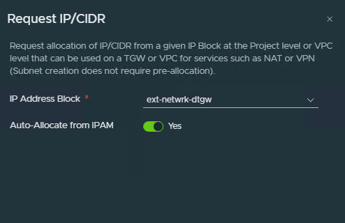
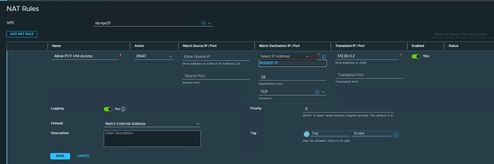 Select the external network IP block to request an IP from.
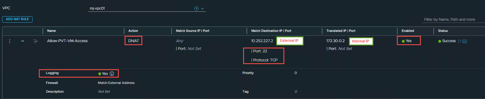
The NAT rule is now created. An external IP “10.252.227.2” is used for network translation, and the translated IP is 172.20.0. 2. Connectivity is allowed on TCP/22, and logging is enabled on the rule to capture the logs for any connection request.
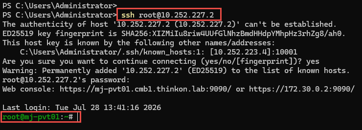
The external VM initiates an SSH connection to the external IP of the VPC’s private VM, and it successfully connects.
The connection details are logged in the firewallpkt.log on the VNA node.

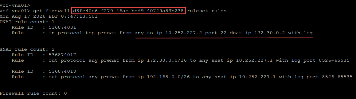
The NAT rule is realized on the VNA node against the VPC’s VRF context
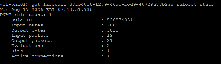
The rule stats can be checked against the service interface of the VPC DR.
Now let’s have a look at the ingress flow from the external VM to the VPC’s private VM.
Note: The overlay transport in the picture is for illustration only. There is no overlay tunnel between the VNA node and the ESXi host. A tunnel is established between the ESXi host and the host on which the VNA node is deployed.

Step 1: The external VM (10.252.80.29) initiates an IP packet (ICMP/TCP) targeting the external IP of the private VM (10.252.227.2).
Step 2: The physical router forwards the packet to the VLAN-backed external network.
Step 3: The packet is intercepted by the Transit Gateway DR component over its external interface (525bbbe0-1a48-4a42-b5ed-340298659371).
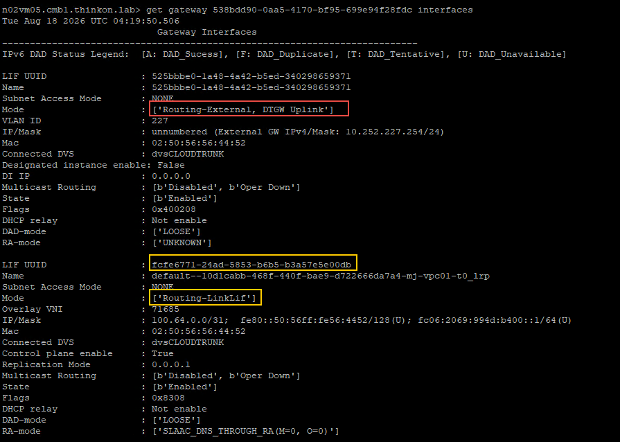
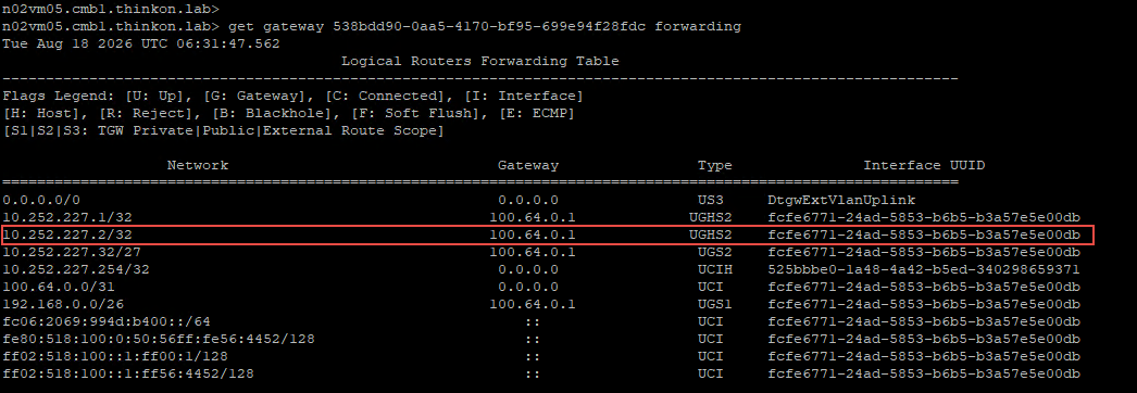
Step 4: The TGW inspects the packet and finds that it is intended for 10.252.227. 2. It checks its forwarding table to determine if a route exists for this destination.
The TGW finds that a direct route to the destination exists over the router-link interface (fcfe6771-24ad-5853-b6b5-b3a57e5e00db), and the neighbor is the VPC Gateway DR component running on the same host. The packet is sent to the VPC Gateway DR.
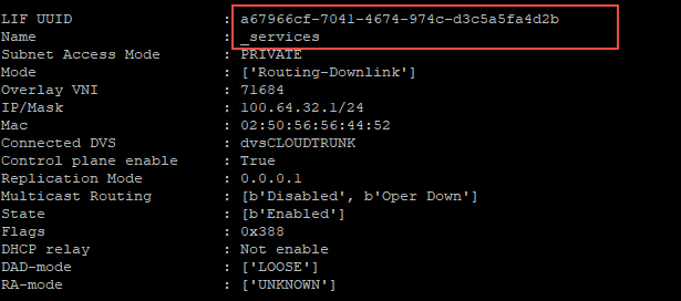
Step 5: The VPC DR component receives the packet, and the VPC Gateway forwarding table is checked to make a routing decision. It finds that it has a direct route to the destination over interface (a67966cf-7041-4674-974c-d3c5a5fa4d2b).
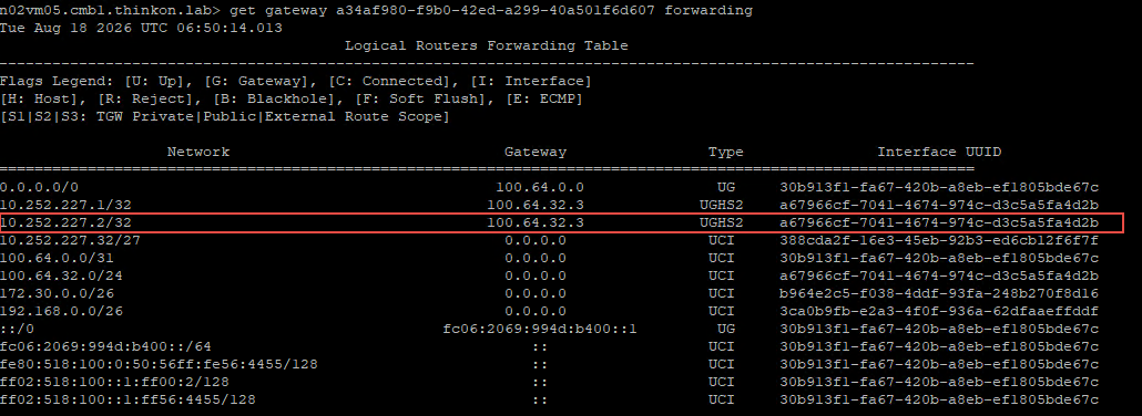
The interface a67966cf-7041-4674-974c-d3c5a5fa4d2b is the service interface on the VPC gateway. The packet is sent over this interface to 100.64.32.3 (VPC SR component).
Step 6: The packet is received by the VPC’s SR component on the VNA node. The VNA node gateway firewall engine evaluates the incoming packet on the service interface against active rulesets and matches Rule ID 536870917. It is determined that the packet is intended for the destination 172.30.0.2
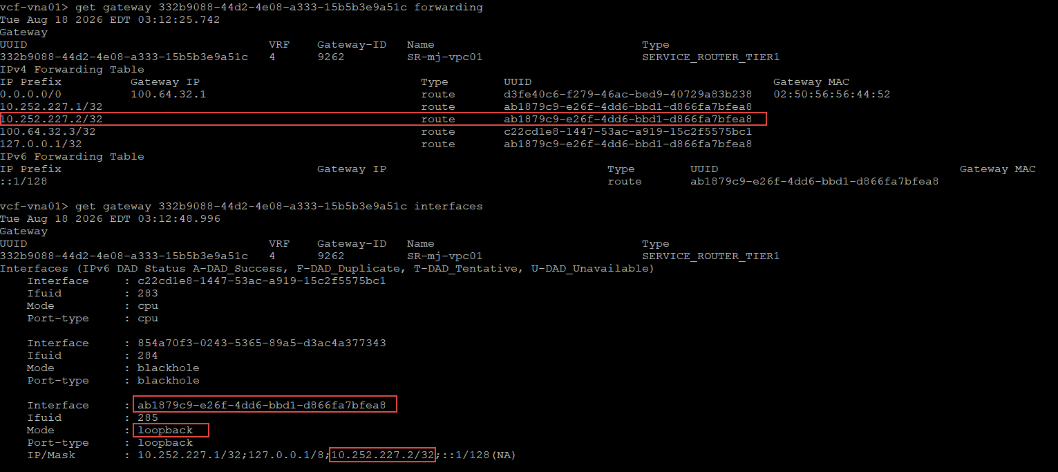
Step 7: The VPC SR component checks its forwarding table to make a routing decision. It finds that a direct route to the destination is present over interface ab1879c9-e26f-4dd6-bbd1-d866fa7bfea8 (loopback)
The packet is encapsulated into a Geneve header and sent back to the VPC DR component. The Geneve packet is sent over the ESXi TEP (source host: hosting VNA node; destination host: hosting private VM)
Step 8: The destination host receives the encapsulated packet, strips the Geneve header, and delivers the original packet to the VPC’s DR component.
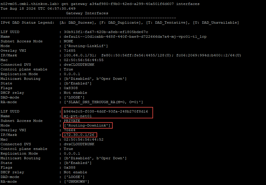
Step 9: The DR component has a downlink LIF connected to the VPC’s private subnet. The packet is routed to the subnet via the default gateway 172.30.0.1.
And that’s it for this post. In the next post of this series, I will demonstrate a packet walk for Inter-VPC communication.
I hope you enjoyed reading this post. Feel free to share this on social media if it is worth sharing.
how are they licensing vna clusters if the stateful services are now being applied there?
Hi James, the VNA nodes/cluster is not licensed separately. It inherits the core VCF licensing the same way as the edge nodes.
Thanks for sharing, what about ingress traffic?
I updated the post today. It has steps for ingress traffic too