
Welcome to part 5 of the VCF-9.1 home lab series. The previous post in this series discussed setting up an offline depot. In this post, I will demonstrate deploying the VCF 9.1 management domain.
If you are not following along, I encourage you to read the earlier parts of this series from the links below:
3: VCF 9.1 Pre-Deployment Planning
4: Setting up VCF 9.1 Offline Depot
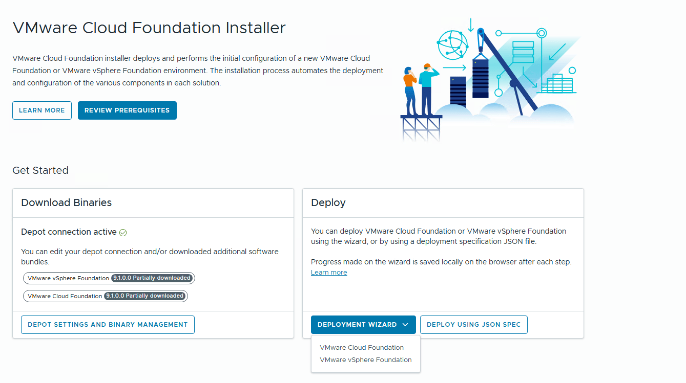
After you configure the depot settings and download the installation binaries to the VCF installer appliance, you start the deployment by clicking the deployment wizard button and selecting the option VCF.
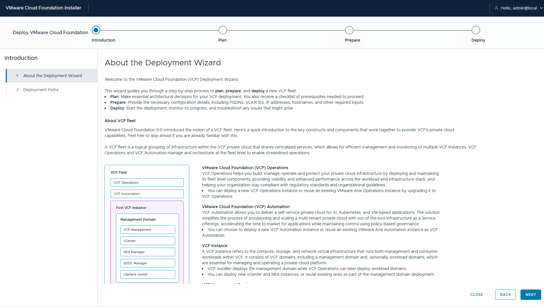
On the introduction page, the very first page is About the deployment wizard, and it provides a high-level overview of the VCF fleet and VCF instances.
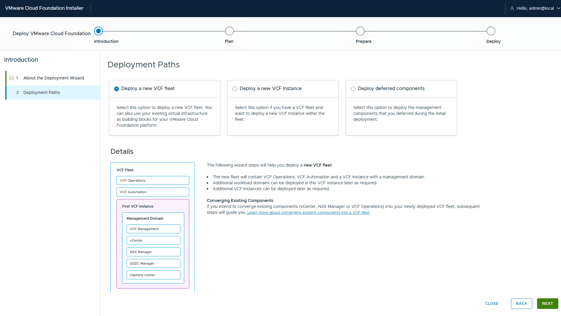
The next screen presents the different deployment paths supported in VCF 9.1. If this is a greenfield deployment, you must select the first option to deploy to a new VCF fleet.
If you already have a VCF fleet in your infrastructure and you are scaling the environment, select the second option, which deploys the additional VCF instance in the existing VCF fleet.
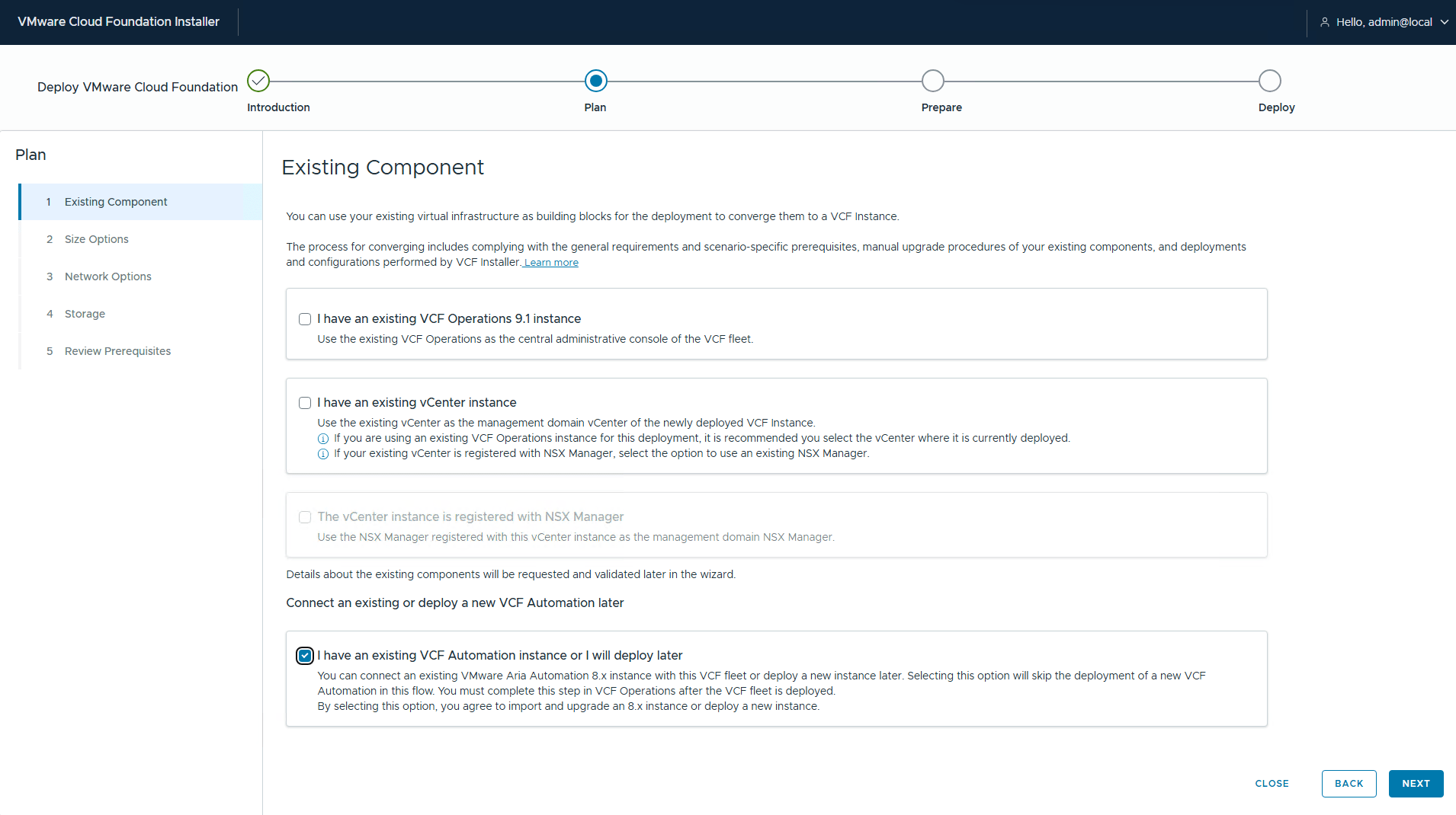
If you already have a vSphere environment (non-VCF), you can import it as a VCF instance. For a greenfield environment, you leave the existing components option unchecked. Also, if you are planning to deploy VCF Automation on day-1/day-2, select the option “I already have an existing VCF Automation instance, or I will deploy later.”
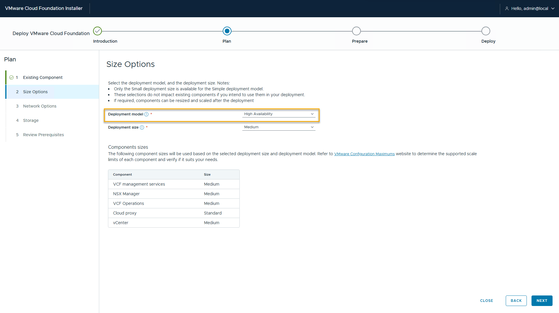
Select the deployment model. For the resource constrainted lab environments, select the simple model and use the small deployment size.
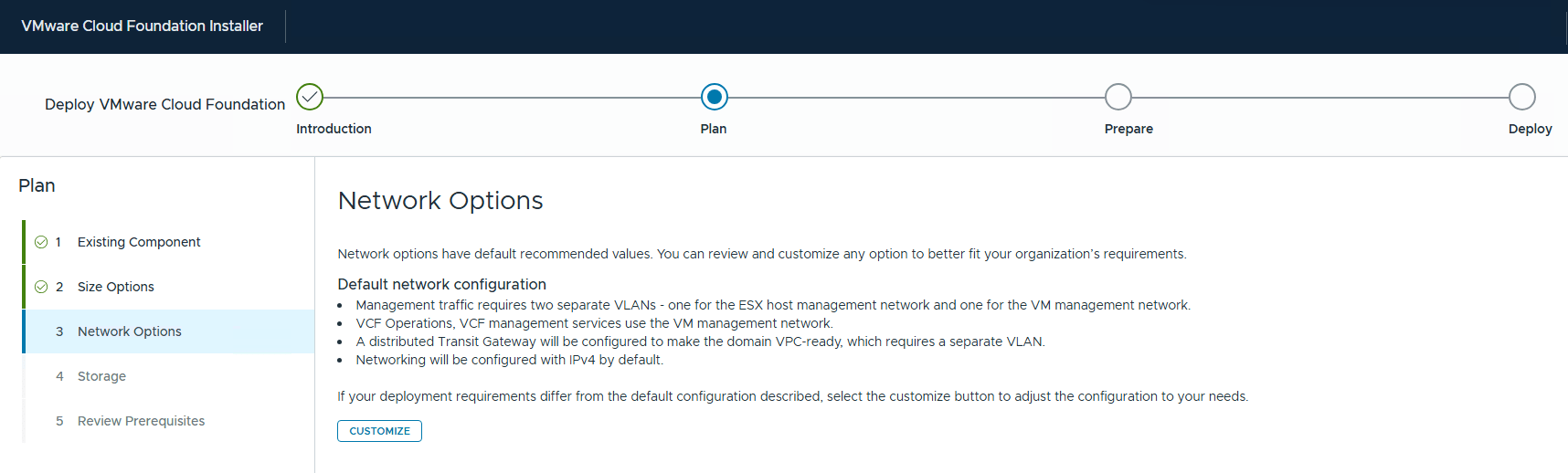
On the network options page, click “Customize” to match the network configuration to your environment.
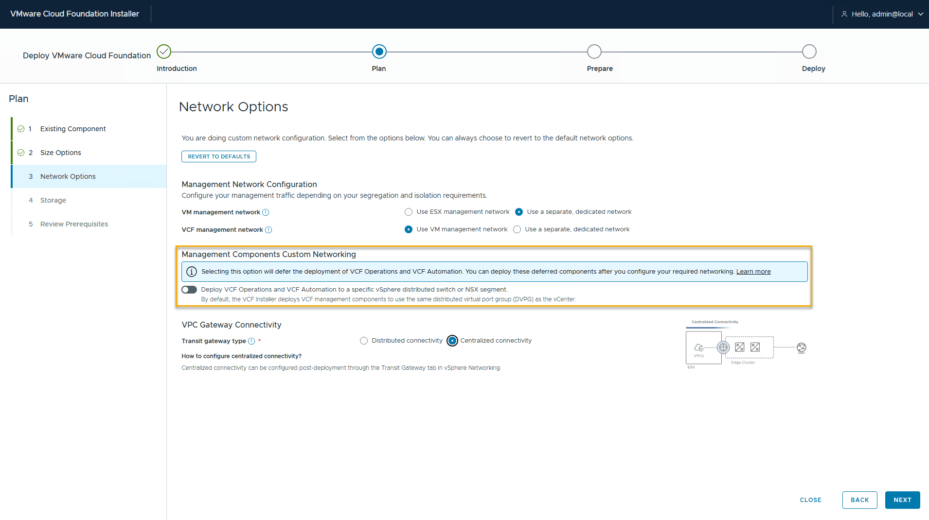
If your ESX management network is different than the infrastructure management network, select the option “use a separate, dedicated network.”
Also, you can choose to deploy the VCF OPS and VCF Automation on a separate VDS or on an NSX segment (AVNs in older VCF versions).
Select the appropriate transit gateway type. If you plan to deploy an edge cluster in the VCF management domain, select the centralized connectivity mode. To learn more about the connectivity type, see my previous blog VCF Networking Models
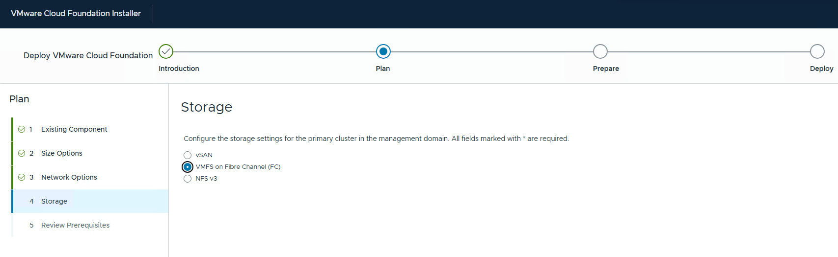
If you want to use vSAN as the principal storage for the management domain, select the appropriate vSAN architecture.
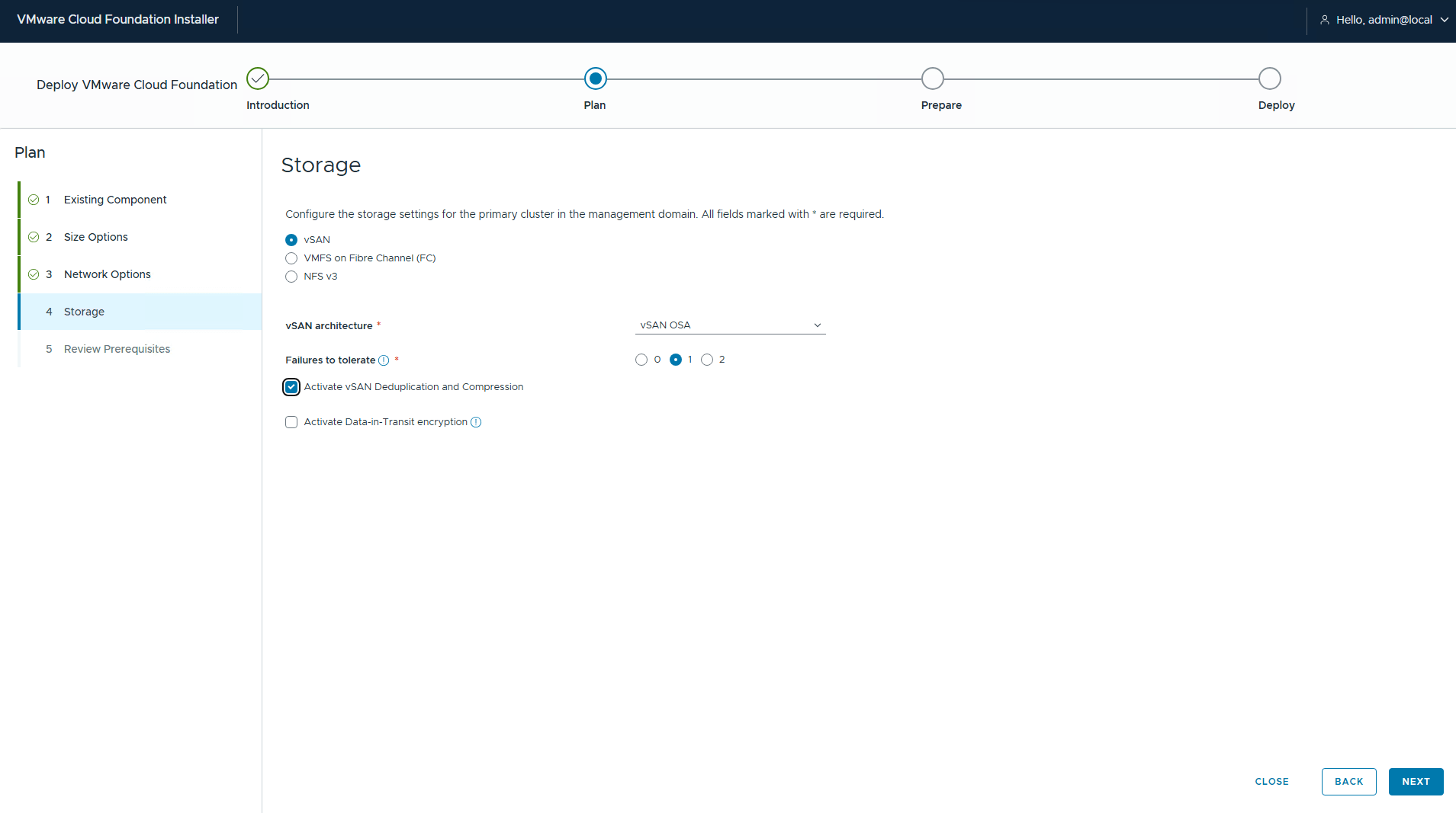
In my lab, I am using Fibre Channel storage.
Review the prerequisites and ensure you have met them in your environment.
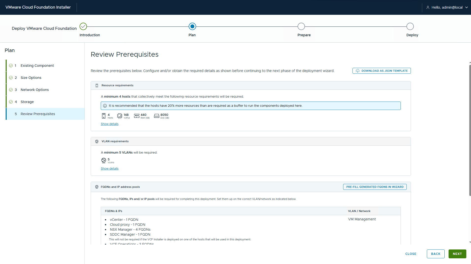
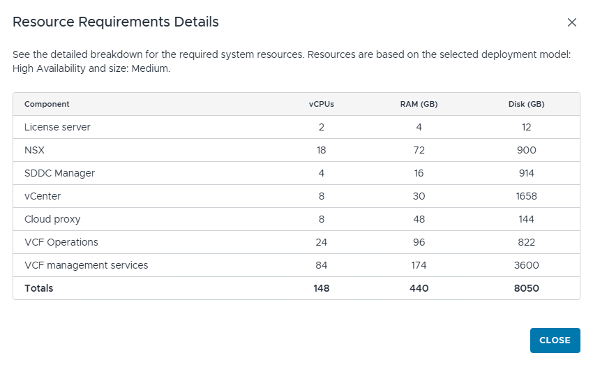
Clicking the “show details” option, the installer displays the vCPU, RAM, and storage requirements.
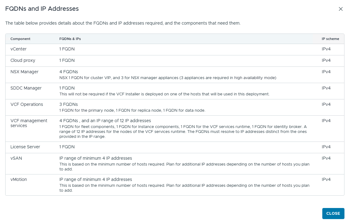
Similarly, you can review the FQDN and IP address requirements.
Click the next button to start the deployment process. The first stage is the preparation stage, where the installer takes the user inputs for building the fleet infrastructure.
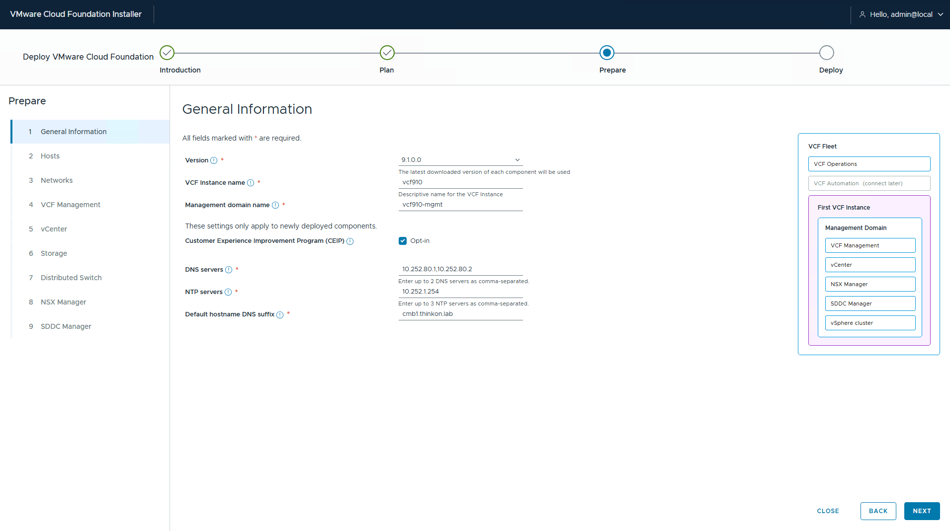
Enter the following information:
- Select VCF version.
- VCF Instance Name
- Management domain name
- DNS servers
- NTP servers
- DNS suffix
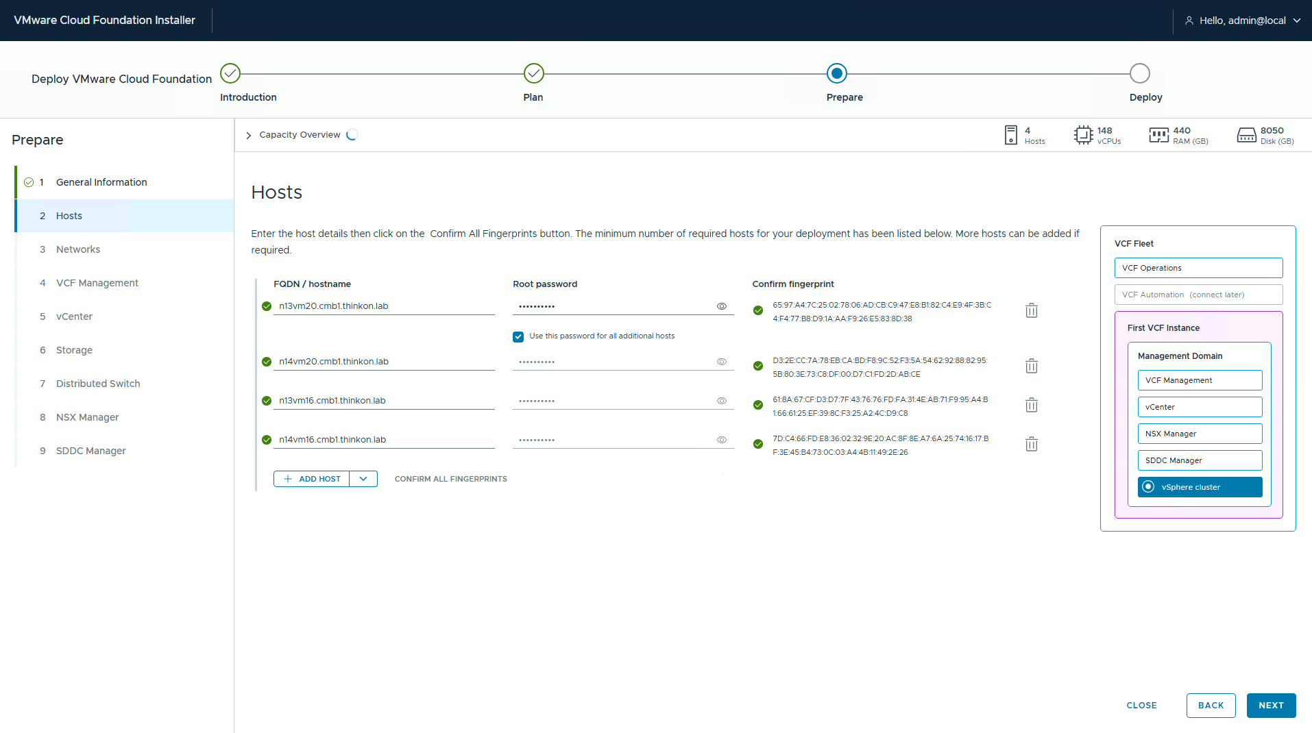
Enter the ESXi host details that will be consumed in the management domain. Confirm the SSL thumbprint (auto-populated) and click Next.
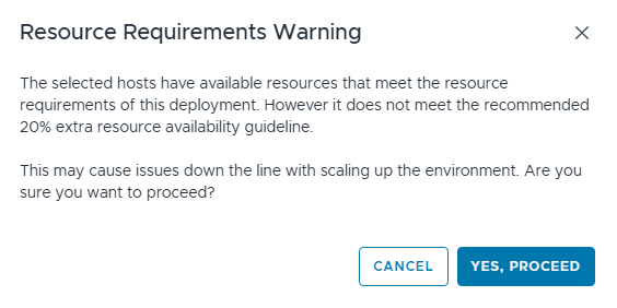
I got a warning that I don’t have an additional 20% resource availability for environment scaling in the future. It was safe to ignore.
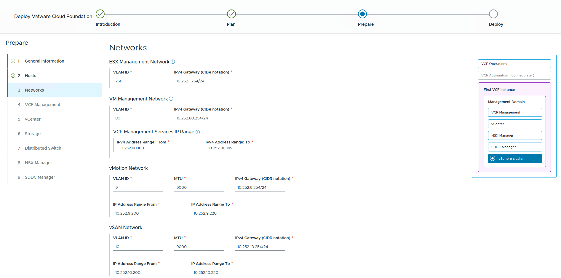
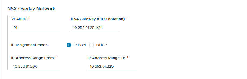
Configure the networking settings as per the VLANs in your infrastructure. This is where the documentation work that you did in the pre-deployment phases comes in handy.
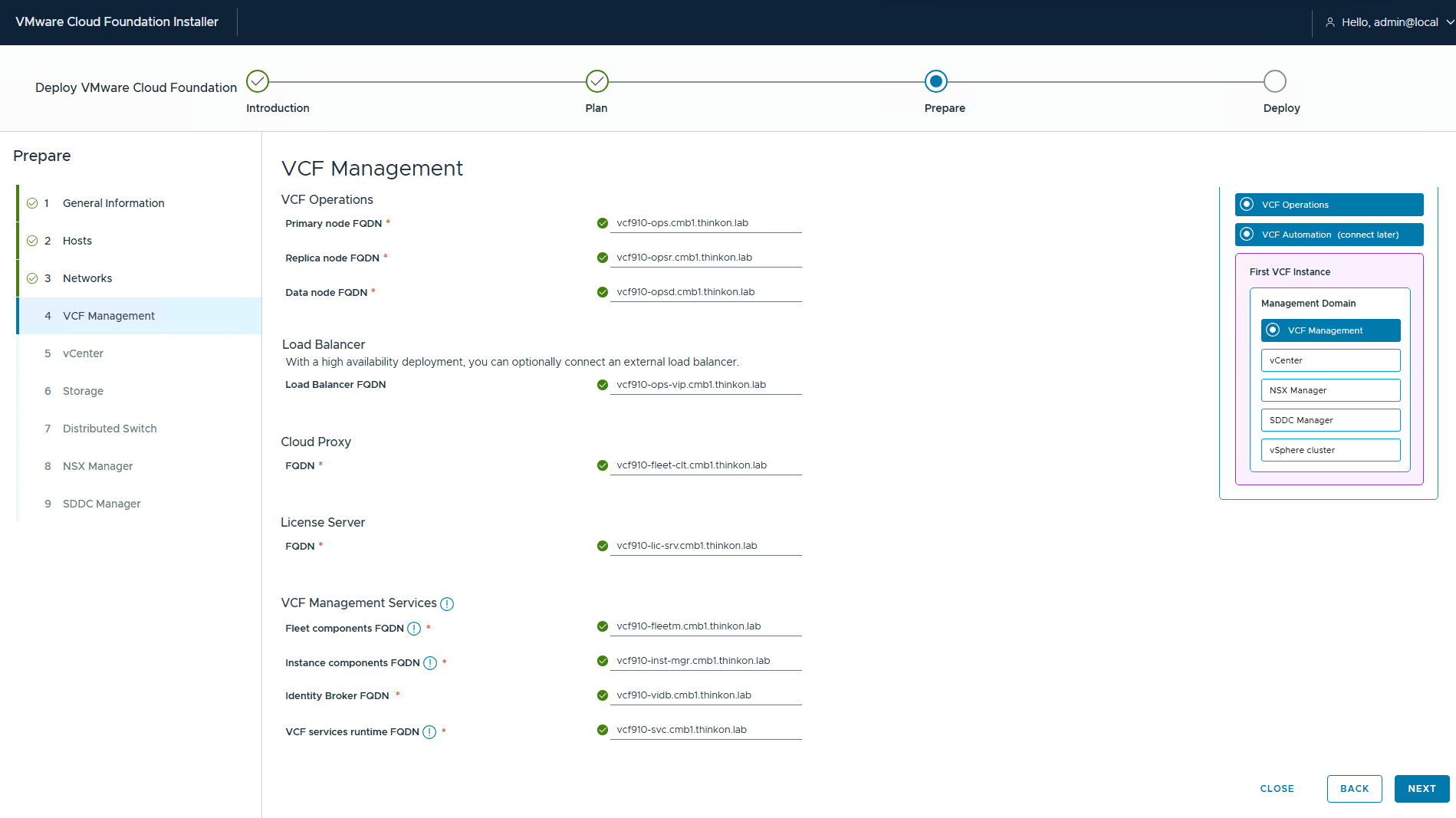
On the VCF management page, enter the required FQDNs. Since the installer doesn’t ask for any IP address, the reverse lookup must succeed from the installer appliance to validate DNS before proceeding.
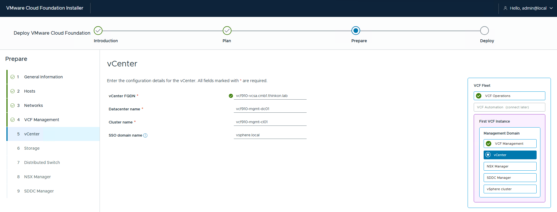
On the vCenter page, enter the vCenter FQDN and specify the name of the virtual datacenter and cluster.
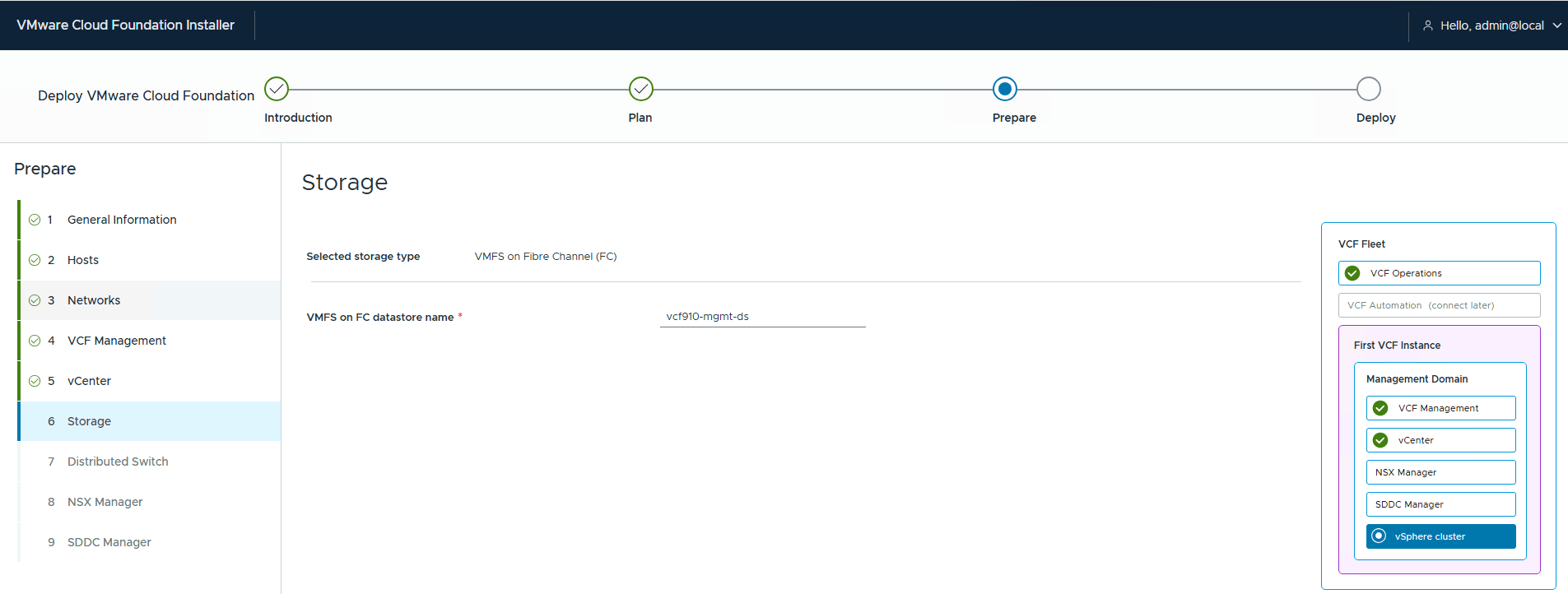
If you are using VMFS on FC, enter the name of the datastore that you want to mount on the management domain hosts.
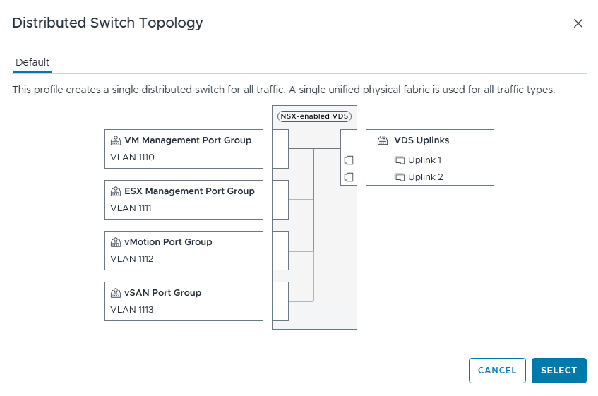
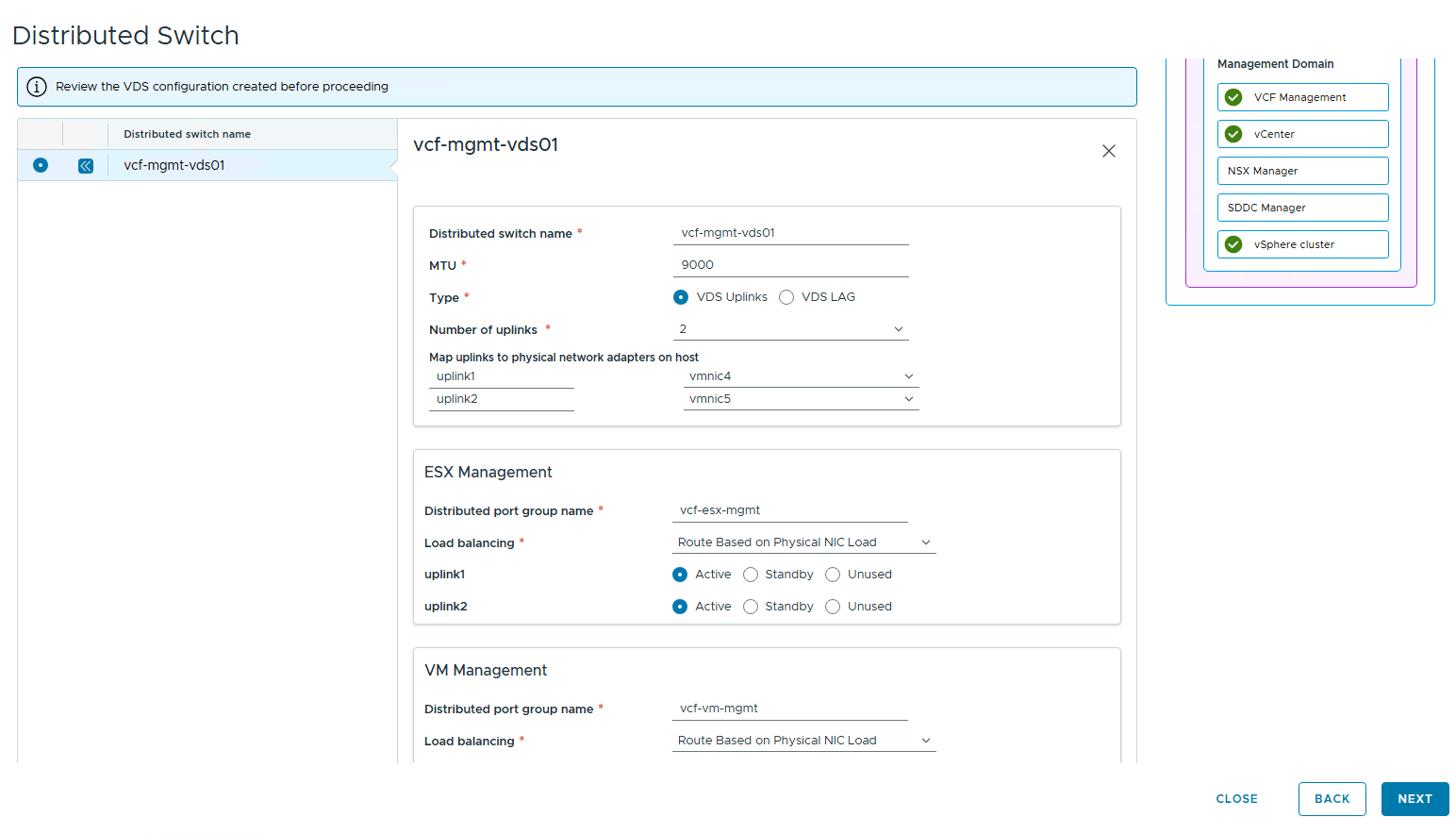
On the VDS page, you can either use the preconfigured default profile or use a custom switch configuration. The default profile is suitable for environments in which hosts have 2 pNICs and all traffic (VLAN + Overlay) traverses over these 2 NICs. If your hosts have more than 2 NICs, you can select the custom switch configuration option.
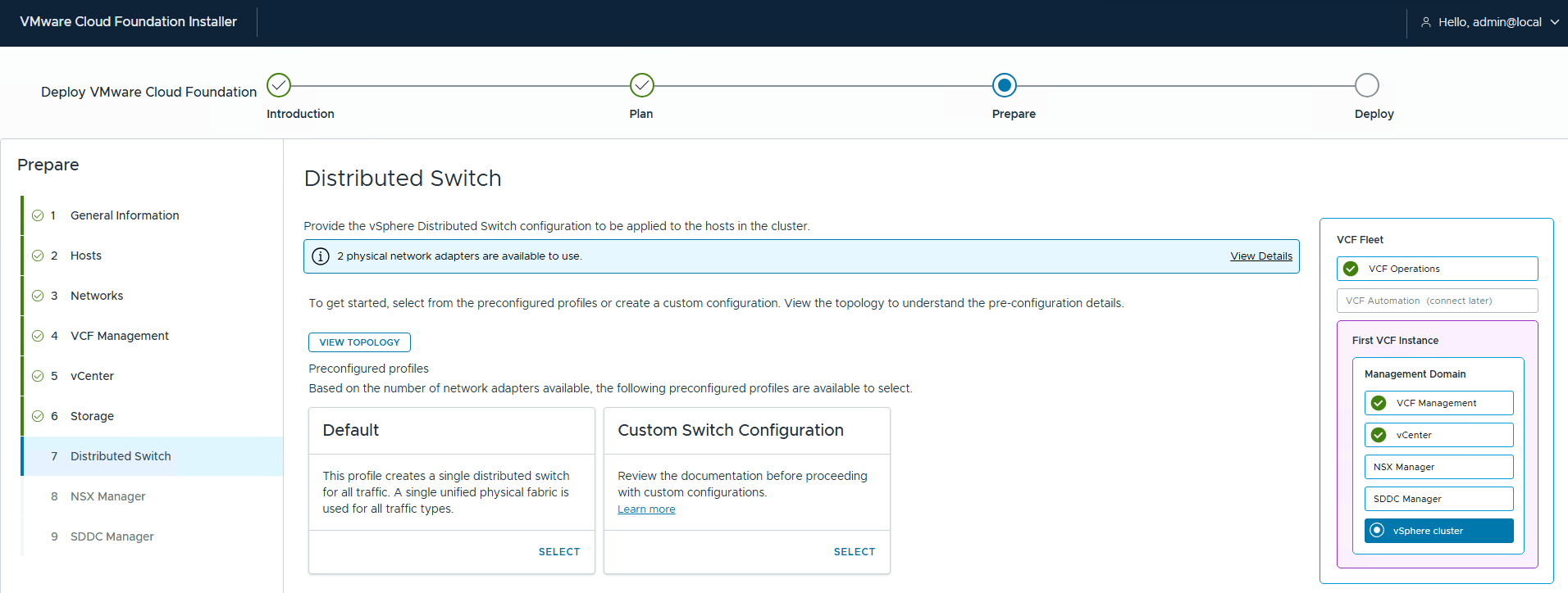
To see the supported topologies, click the View Topology option.
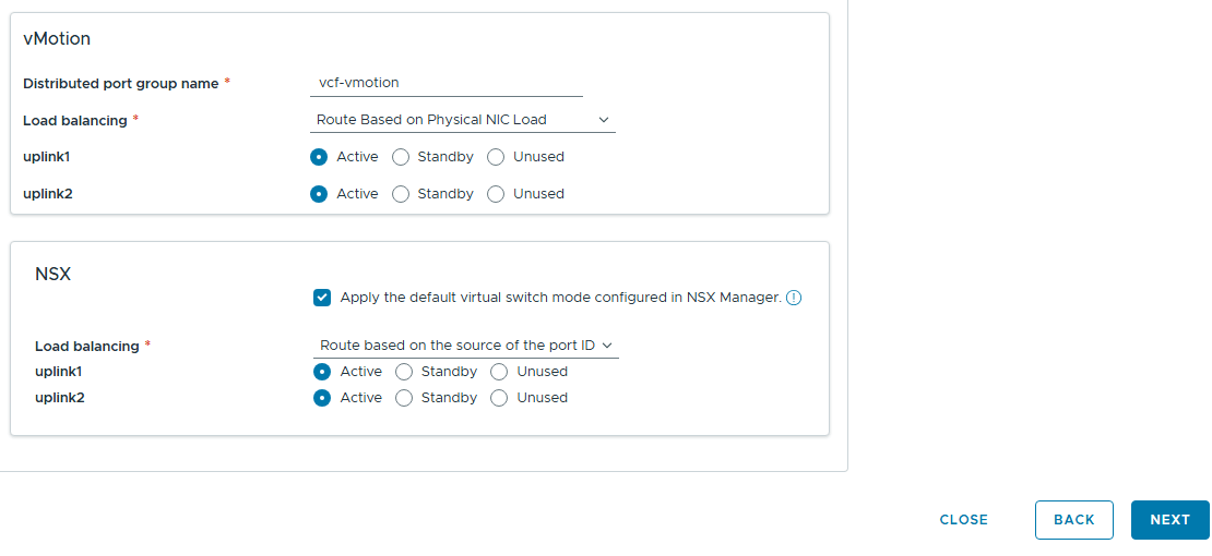
If you choose to use a custom configuration, enter the switch details and the distributed portgroup details manually.
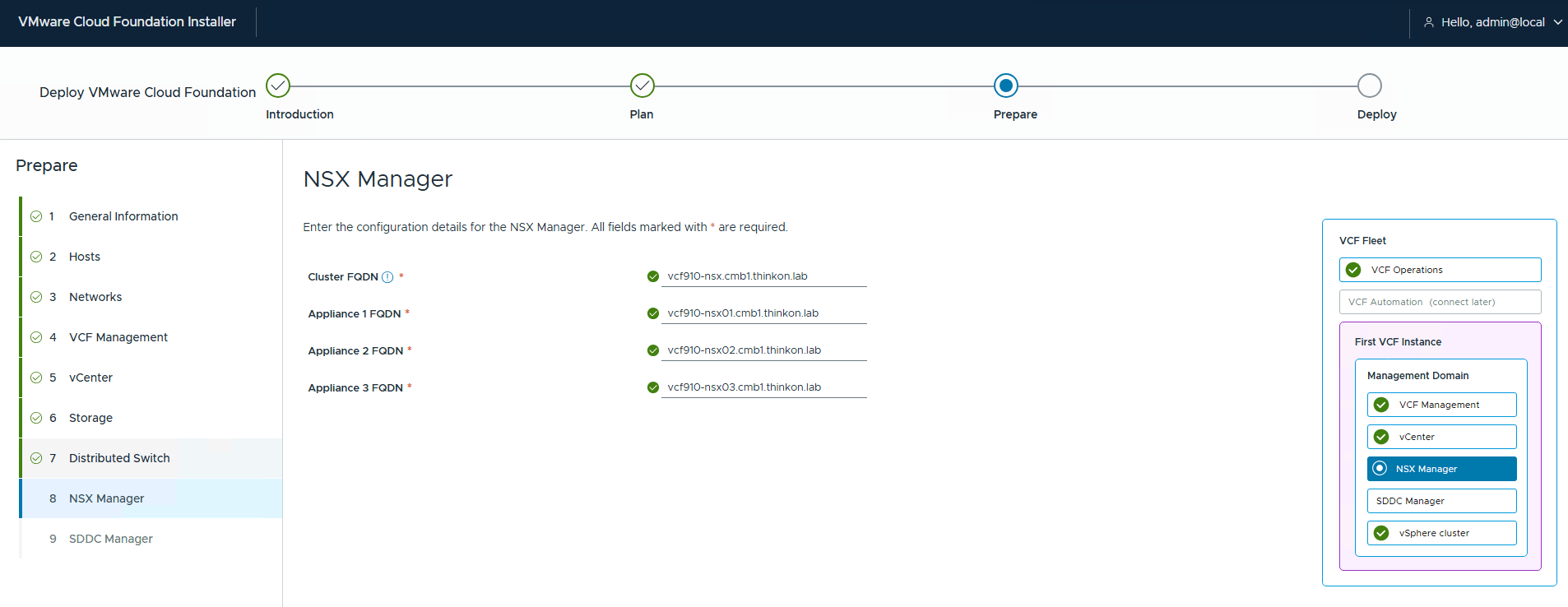
Enter NSX VIP/Node FQDNs and click Next.
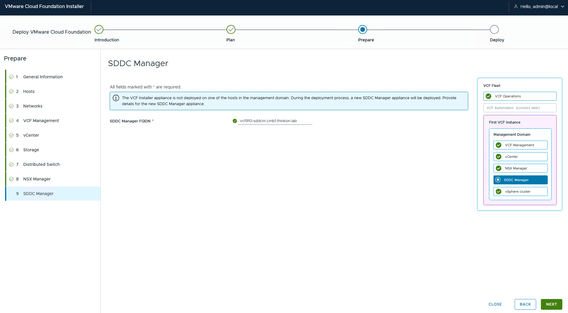
Enter the SDDC Manager FQDN and click Next.
On the summary page, expand the component options and ensure the inputs are correct. You can download the JSON spec for reusability and automation purposes.
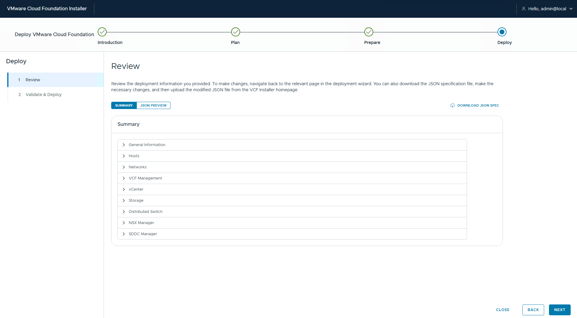
Click next to start the input validation.
After the validation stage is completed, click the Deploy button to initiate the fleet deployment.
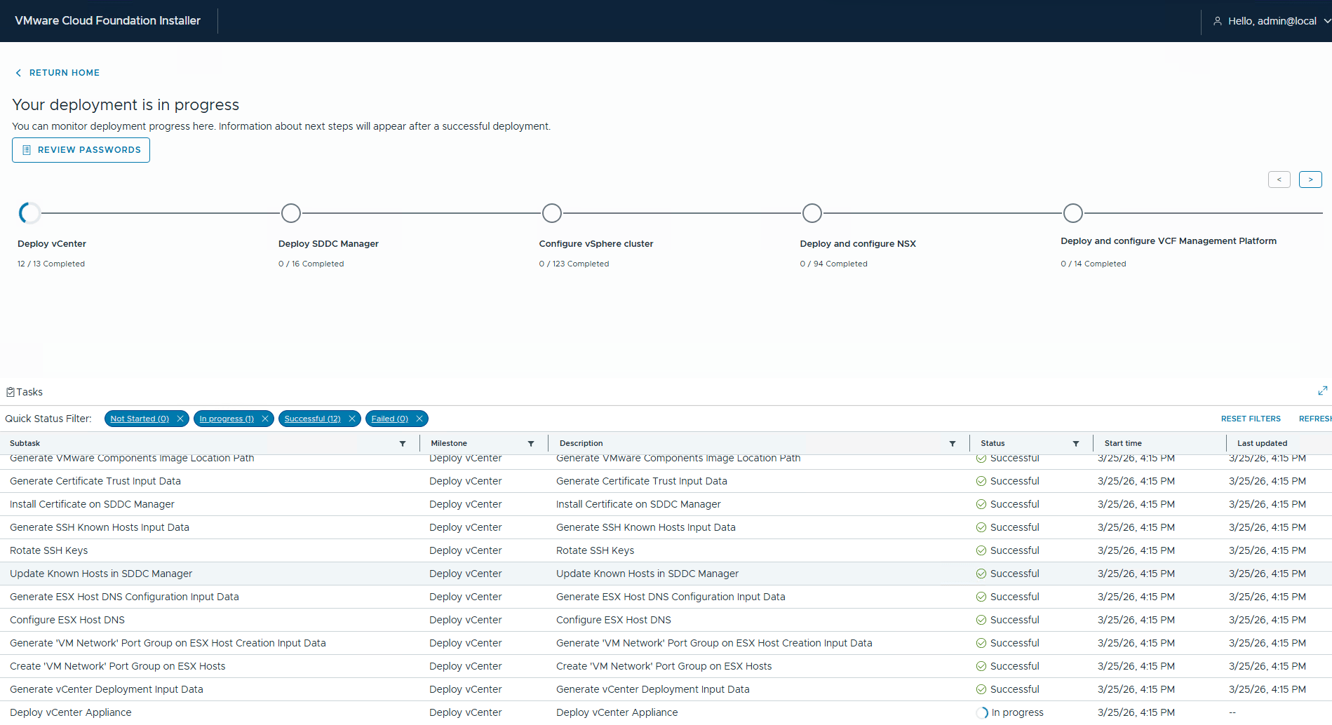
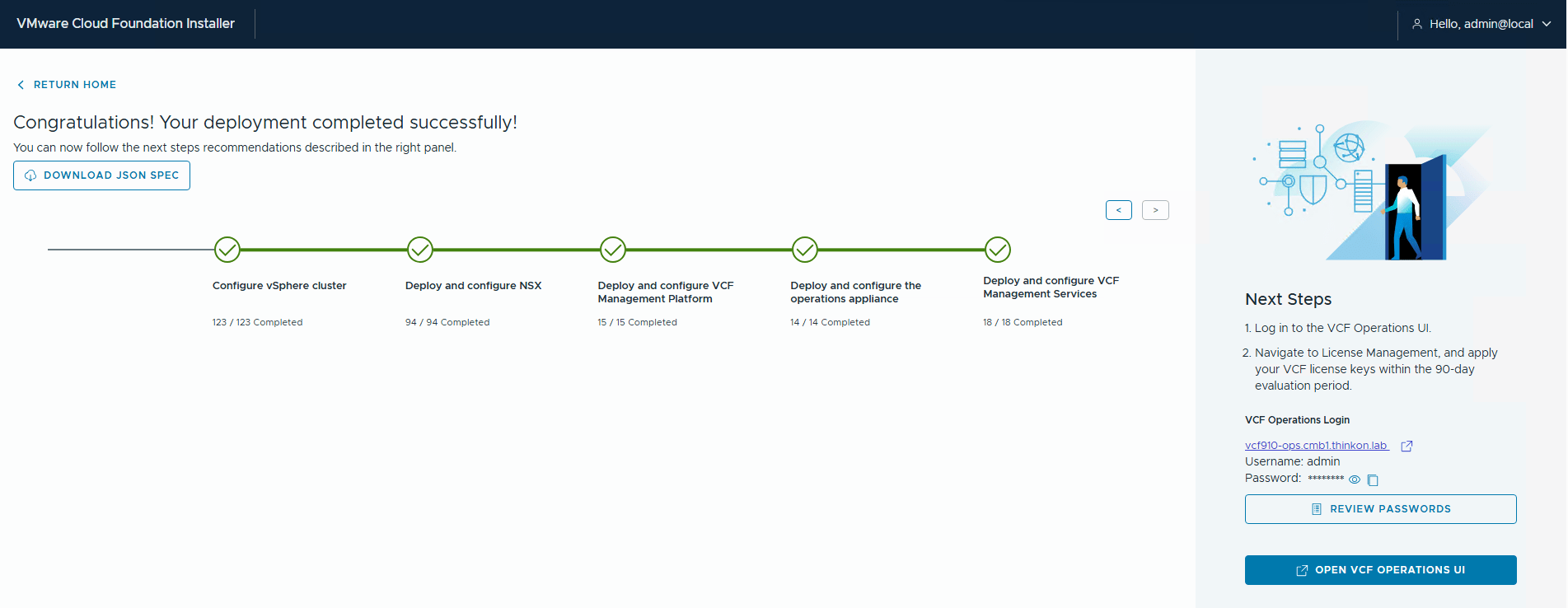
Sit back and relax. It takes a while (4-6 hours) for the fleet deployment to complete. Since the installer UI auto-generates passwords for all components, click the review passwords button to see the password.
And that’s it for this post. In the next post of this series, I will discuss the management domain’s network connectivity setup.
I hope you enjoyed reading this post. Feel free to share this on social media if it is worth sharing.