
Welcome to part 11 of the VCF-9.1 home lab series. The previous post in this series discussed deploying a new instance of VCF Automation. In this post, I will demonstrate provider management configuration.
If you are not following along, I encourage you to read the earlier parts of this series from the links below:
3: VCF 9.1 Pre-Deployment Planning
4: Setting up VCF 9.1 Offline Depot
5: VCF 9.1 Deploy Management Domain
6: Configure Management Domain Network Connectivity
8: Enable Avi on Workload Domain
9: Deploy Supervisor in Workload Domain
In VCFA, objects are categorized under provider and organization. The provider admin creates organizations (tenants) and resources that these organizations can consume. VCFA supports two different types of organizations:
- All-Apps: Requires a supervisor and supports running VMs and container workloads.
- VM-Apps: Only supports running VMs (the old Aria Automation way)
The diagram below shows the high-level architecture of the VCFA.

The Provider Management in VCFA refers to adding resources to the system and enforcing quotas and guardrails for fair consumption by organizations. The system administrator must configure the system end-to-end before it can be consumed by the tenants. The system/provider admin is responsible for managing the overall infrastructure, services, and tenancy model across multiple organizations or tenants.
The key responsibilities of a provider admin are:
- Defining Regions (mappings between VCF Automation and vSphere Supervisors).
- Creating external networks for outbound connectivity.
- Configuring placement policies and region quotas at the infrastructure level.
- Configuring networking quota for the organizations.
- Organization onboarding and lifecycle management.
- Managing content libraries and VM image repositories.
The section below covers these tasks in more detail. For configuring these tasks, you must connect to VCFA by typing https://vcfa-fqdn>/provider and login with system admin credentials.
Upon first login, you are presented with a couple of options for performing the provider management tasks. You can either do a Quick Start to set up a single tenant or do a Manual Setup to create a multi-tenant architecture. I will demonstrate the manual setup here.

A guided workflow opens up for setting up the VCFA constructs one by one. Once you finish a step, mark it as complete and go to the next step.

Step 1: Create Region
A region is the provider-level construct that groups together compute, storage, and networking resources from the underlying infrastructure and makes them available for tenant consumption. It’s essentially the bridge between VCF Automation and the physical SDDC layer. It is created by grouping one or more supervisors from one or more vCenter instances, but all supervisors in the region must be configured under the same NSX Manager.
Click the Start button to create a new region.

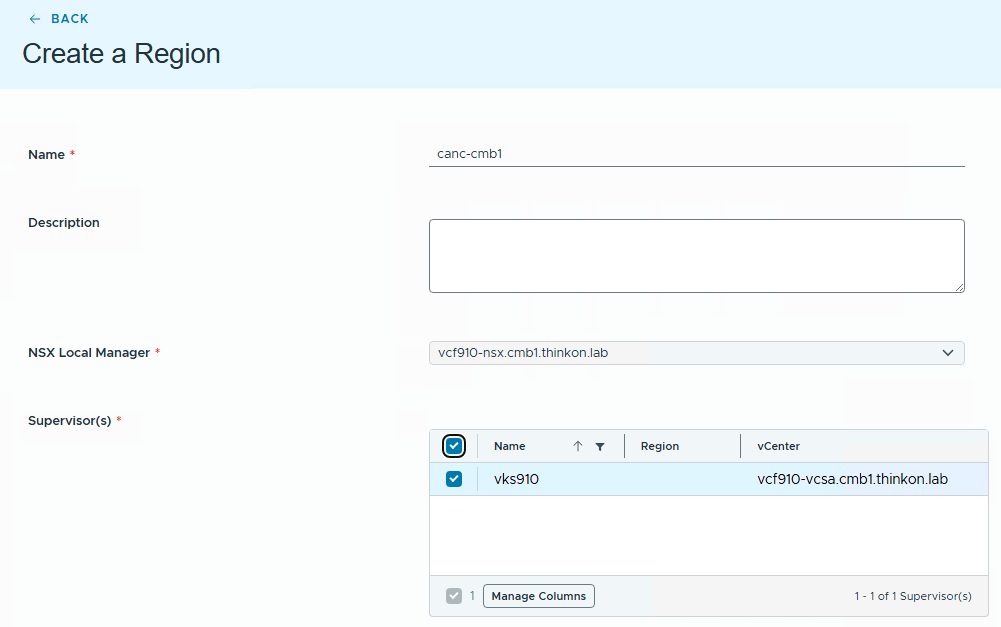
Specify the region name and select the NSX Manager that will participate in the region. The system identifies the supervisor tied to this NSX. Select the supervisor and click next.
Select the storage classes from the list of available classes and click Submit.

Wait for the region creation to complete and the status to report Ready.

Step 2: Create External IP Block
The external IP block is the pool of routable IP addresses north of the tier-0 gateway that VCF Automation draws from to provide tenant workloads with external reachability. It’s the “public” side of the network from the tenant’s perspective. The external IP block gets assigned to the tier-0 gateway (provider gateway) and is advertised to the ToR or firewall via BGP.
The external IP block enables the SNAT functionality for the tenant workloads. Also, if Avi is enabled for the organization, the load balancer VIP comes from this pool. From a CSP POV, the external IP block is a range of public IP addresses.

Specify the name for the external IP block and select the region where this block will be available for tenant consumption.

The IP block can be configured either by providing the network CIDR or specifying a range of addresses. You can also specify reserved IP ranges to be excluded from the pool of IP addresses and CIDRs available for allocation.
If your organization uses a third-party IPAM solution like Infoblox, you can configure it here, but you must register Infoblox with NSX first. See Register Infoblox with NSX

Configure the IP quota for the organizations. This ensures that each tenant only gets what they have subscribed to.

Review the settings and click Create.

Wait for the IP block creation task to complete.

Step 3: Create External Connection
An External Connection in VCF Automation is the provider-defined, abstracted path from the virtual network (tenant VPCs and Transit Gateways) out to the physical network. It is the “on-ramp” that connects everything happening inside the NSX overlay to the real world.
The provider defines external connections, such as centralized or distributed VLAN/VXLAN connectivity. These external connections represent abstracted paths to the physical network. Once created, external connections are made available to tenants. Tenants can then use them to connect their transit gateways without needing to understand the underlying physical network design.

Specify the external connection name and select the region where this connection will be made available. Click Next.

Select the tier-0 gateway from the list. The external connection can be configured to use either centralized connectivity or distributed connectivity. In my lab, a centralized transit gateway connection is configured for external connectivity.

Select the external IP block that you created in the previous step and enable “Insert Provider Outbound NAT”.

Select the CIDR that will be used for auto SNAT configuration.

Configure the remote network settings. If you leave the settings to the default value, 0.0.0.0/0 will act as the default gateway for the external connection. You can also specify specific CIDRs that can be reached from this external connection by adding the CIDRs here.

Review the settings and click Create.

Wait for the external connection creation task to complete.

Step 4: Create Organization
An organization serves as the top-level administrative entity for grouping and managing resources, users, policies, IaaS services, and catalog objects, while maintaining clear security and operational boundaries from other organizations.
It provides a centralized framework for access control, billing, and resource allocation, enabling effective governance, collaboration, and management across teams and business units.

Select the organization type and click Next.

Name the organization and click Create and Continue.

Select the region from the list and enforce the quota by selecting the “share a portion of capacity” option.

Click Add capacity and select the zone where the quota will be enforced. Specify the CPU/memory allocation and reservation.

Click Assign and Continue.

Add the VM classes and storage classes and configure the storage limit. Each VM class is configured to use X amount of CPU and Y amount of RAM. Click Assign and Continue.

Under networking, select the external network for the organization and choose the edge cluster to which that external network is tied.

Create the first user for the organization and assign the Organization Administrator role to the user. This user can further create new users and assign appropriate roles from the organization portal.

Wait for the organization creation task to complete and the creation status reporting to be ready.

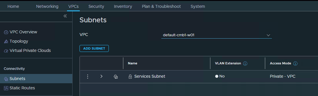
Under the hood, VCFA creates a project in NSX.

A default VPC is created under the organization’s project.

A subnet is also created in the VPC.
Lastly, the organization admin can login to the tenant portal by connecting to https://>vcfa-fqdn>/tenant/<org-name>/ and using the credentials provided by the provider admin.

And that’s it for this post.
In the next posts of this series, I will cover more topics on VCFA. Stay tuned!!!
I hope you enjoyed reading this post. Feel free to share this on social media if it is worth sharing.