
Welcome to part 13 of the VCF-9.1 home lab series. The previous post in this series discussed deploying and configuring VCF Logs. This post will discuss VNA clusters in detail, including the deployment.
If you are not following along, I encourage you to read the earlier parts of this series from the links below:
3: VCF 9.1 Pre-Deployment Planning
4: Setting up VCF 9.1 Offline Depot
5: VCF 9.1 Deploy Management Domain
6: Configure Management Domain Network Connectivity
8: Enable Avi on Workload Domain
9: Deploy Supervisor in Workload Domain
11: VCFA Provider Management Configuration
12: Deploy VCF Operations for Logs
VCF 9.0 introduced a public-cloud-style consumption model for networking: instead of designing tier-0/tier-1 gateways by hand, tenants and application teams get Virtual Private Clouds (VPCs) with self-service subnets, routing, and security. Underneath the VPC abstraction sits a routing construct called the Transit Gateway (TGW), which can operate in two modes:
- Centralized Transit Gateway (CTGW): Routing and stateful services (NAT, load balancing) are anchored to a classic NSX Edge cluster, exactly as with a traditional Tier-0.
- Distributed Transit Gateway (DTGW): Routing happens directly on ESXi host transport nodes, with no dependency on Edge VMs. Traffic stays local to the hypervisor, which is great for east-west performance and operational simplicity.
I covered this in detail in my VCF 9.0 blog: VPC Networking Models
The catch in VCF 9.0: DTGW was routing-only. If you needed stateful services such as NAT, load balancing, or VPN, you had to fall back to a centralized transit gateway backed by an edge cluster, which reintroduced the very complexity DTGW was meant to remove.
VCF 9.1 closes that gap with the Virtual Network Appliance (VNA) cluster, which is a new, purpose-built appliance framework that brings stateful services to distributed VPC environments without requiring a full edge cluster or classic T0/T1 design.
Many customers, especially those adopting VCF primarily to run VMware Kubernetes Service (VKS) workloads, wanted the operational simplicity of DTGW and the service richness of CTGW. VNA is Broadcom’s answer: a lightweight, horizontally scalable appliance cluster that plugs into the distributed model and hosts the stateful data plane, while routing itself remains distributed on the hosts.
This post is a deep dive into VNA cluster architecture, how it’s deployed, and where it fits in your VCF 9.1 design.
What Exactly Is a VNA Cluster?
A VNA (Virtual Network Appliance) is, under the hood, built on the same logic as an NSX Edge appliance, but its role and network attachment are substantially different and purpose-built for VPC service delivery rather than general T0/T1 routing. A VNA cluster is:
- A pool of one or more VNA appliance VMs deployed directly from vCenter/NSX.
- Attached to an NSX Project, and from there made available to distributed transit gateways and the VPCs that connect to them.
- Responsible for the stateful functions that distributed routing cannot perform on the host data plane alone: advanced NAT, Layer 4 load balancing, and (in centralized-connectivity scenarios) IPsec VPN.
Deployment feels intentionally familiar: you pick a form factor (the same small/medium/large sizing options used for Edge clusters), specify vSphere cluster and datastore placement, and add nodes; the workflow mirrors classic Edge cluster deployment closely enough that existing NSX admins won’t need to relearn much.
Before moving ahead in this post, let’s pause and see a comparison between the VNA and the Edge cluster.
| Aspect | NSX Edge (Centralized) | VNA (Distributed Services) |
| Routing model | Hosts Tier-0/Tier-1 SRs, classic BGP/static routing. | Routing stays distributed on hosts (DTGW); VNA hosts services only |
| TEP network | Own dedicated TEP | Uses host TEP network |
| Switch/N-VDS config | User-configurable | Pre-defined, read-only, auto-attached |
| Services supported | Full: stateful FW, NAT, LB, VPN, BGP | DHCP, NAT, L4 LB, and VPN in centralized-connectivity scenarios |
| Scale | Typically 2 nodes per cluster (active/standby or ECMP) | 2–10 nodes per cluster |
| Primary use | Traditional T0/T1 designs, full dynamic routing | VPC-centric, DTGW-attached, simplified consumption |
VNA Architecture
So how is a VNA cluster different from an edge cluster? The answer lies in the architecture of the VNA cluster.
Data Plane: Fastpath Interfaces and Pre-defined N-VDS
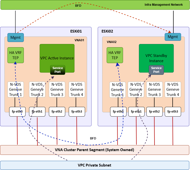
Each VNA appliance ships with four Fastpath interfaces, and each of those interfaces connects to an N-VDS GENEVE trunk. Unlike a traditional edge node, where you configure switches, uplinks, and TEP interfaces yourself, the N-VDS instances backing a VNA are pre-defined and read-only. There is no manual switch configuration step.
Each FastPath interface automatically attaches to a parent overlay segment that NSX creates specifically for that VNA cluster. If you deploy more than one VNA cluster in your environment, NSX creates a dedicated parent overlay segment per cluster; these segments are system-managed and cannot be edited directly.
The parent segment does two jobs:
- It carries the BFD session between the HA VRF instances running on each VNA appliance (over fp-eth0), which is what drives failover detection.
- It distributes traffic for VPC service subnets — i.e., the actual north-south/stateful-service traffic that VPCs route through the VNA.
No Independent TEP Network
A classic Edge VM maintains its own TEP network for overlay encapsulation. VNA does not. Instead, it rides on the host TEP network of the ESXi transport node it runs on. This is a deliberate design choice that keeps the VNA lightweight and tightly coupled to the distributed data plane model. It consumes the same overlay fabric that the hosts already participate in, rather than standing up a parallel encapsulation domain, as Edge clusters do.
The following diagram shows the architecture of the VNA Cluster.
VNA Use Cases
The following are the use cases for VNA:
Stateful Services for Distributed VPCs
VNA provides distributed transit gateways access to NAT and Layer 4 load balancing without forcing a redesign around a centralized edge. Before 9.1, DTGW customers were stuck with DHCP and only basic external NAT.
VPC Load Balancing
VCF 9.1 introduces the Load Balancer as a VPC service, running as a dedicated workload on top of a VNA. L4 load balancing is fully supported and runs isolated within the VNA, which VMware positions as improving scalability, flexibility, and service isolation compared to bolting LB onto a general-purpose edge.
VMware Kubernetes Service with VPCs
Previously, using VKS with VPC-style networking effectively required an Edge cluster and a full T0 design. VNA removes that dependency—VKS can now run against a distributed, VNA-serviced VPC, which is a meaningful simplification for platform teams standing up KaaS on VCF.
Multi-Tenant, Multi-Gateway Designs
VCF 9.1 also enables multiple Transit Gateways per tenant, each with distributed VLAN connections, isolated VPNs, static routes, and custom NAT—giving tenants flexible multi-site routing and traffic management without external routing hardware. VNA clusters are the shared service layer that makes the stateful pieces of these designs possible.
Self-Service Networking for Teams Resistant to Classic NSX
Because a routable VLAN plus a VNA cluster gets you most of the benefit of a centralized design with a fraction of the routing protocol complexity, VNA lowers the barrier for teams who have historically been hesitant to adopt NSX, Tier-0 gateways, and dynamic routing (BGP).
Design Considerations and Best Practices
- Size for HA, not minimums. Two nodes is the minimum requirement, not necessarily the right production number—plan node count against expected NAT/LB throughput and failure-domain requirements.
- Because VNAs participate in north-south traffic forwarding, placement matters. Broadcom recommends spreading VNA appliances across hosts using strict anti-affinity rules so a single host or cluster failure doesn’t take down the whole VNA cluster.
- Plan your external IP blocks up front. External connectivity depends on an IP address block explicitly marked “External”—an easy step to miss.
- Know the licensing boundary. Self-service NAT, VPN, and grouping/firewalling are available under VPCs, but Stateful Gateway Firewall (GFW) and Distributed Firewall (DFW) require a vDefend Firewall license—factor this into your BOM if security services are part of the design.
- VNA doesn’t replace Edge everywhere. Centralized Transit Gateways and classic Edge clusters remain the right choice for full dynamic-routing designs (BGP-heavy multi-site topologies, stateful firewalling at scale)—VNA specifically targets the distributed/VPC consumption model.
VNA Cluster Deployment
The deployment of a VNA cluster can be triggered from both vCenter and NSX Manager. The deployment steps remain the same. I deployed the cluster in my lab using the vCenter UI.
In the vCenter UI, select the vCenter instance and navigate to Configure > Networking > VNA Clusters and click Add Cluster.

Type the cluster name and choose the cluster form factor. To add a node to the cluster, click Add.

Enter the node FQDN and select the compute and storage placement for the node.
For the management network, I used the infrastructure management network where other infra endpoints are deployed.

To add another node to the cluster, select the first node and click Clone.
It’s worth noting that the passwords for the VNA cluster nodes are auto-generated and can be retrieved from VCF OPS/SDDC Manager.

Specify the second node FQDN and IP details and click Apply.

Click Save to trigger the deployment.

The deployment roughly takes 10-15 minutes to complete.

Wait for the connectivity status to report success.

Behind the scenes, a new parent overlay segment is created for VNA.

The VNA nodes’ fastpath interfaces get hooked to the parent segment.

Conclusion
The VNA cluster is arguably one of the more consequential networking additions in VCF 9.1: it takes the Distributed Transit Gateway from “routing-only” to “feature-complete for most VPC use cases” without dragging back in the operational weight of a full Edge/Tier-0 design. For platform teams building self-service VPC-style networking, especially those running VKS, VNA is likely to become the default way stateful services get delivered, with Centralized Transit Gateways reserved for the minority of designs that genuinely need full dynamic routing or advanced stateful firewalling at the gateway.
Now the VNA cluster is ready. But how do I consume this? The answer is Distributed Transit Gateway in a VPC. I will cover this topic in the next series of this blog. Stay tuned!!!
I hope you enjoyed reading this post. Feel free to share this on social media if it is worth sharing.