
In my NSX-T 3.0 series, I wrote an article on setting up logical routing so that traffic can start flowing through the SDDC.
If you have missed my NSX-T 3.0 series, here are the links to the same:
1: NSX-T Management & Control Plane Setup
3: Transport Zones & Transport Node Profiles
5: Configure Logical Routing in NSX-T
Let’s do a quick recap on routing capabilities in NSX-T.
Logical Routing in NSX-T has the ability to provide connectivity for both virtual and physical workloads that are in different logical L2 networks. Workloads get connected via segments, and these segments can, in turn, attach to a T0/T1 GW for east-west & north-south communication.
T0/T1 gateways have Service Routers (SR) & Distributed Routers (DR). The DR component is embedded at the hypervisor level and ‘abstracted’ from the underlying physical network.
In NSX-T, we have 2 ways of achieving logical routing:
- Single-Tier Routing
- Multi-Tier Routing
In this post, I will discuss single-tier routing.
Single-Tier Routing
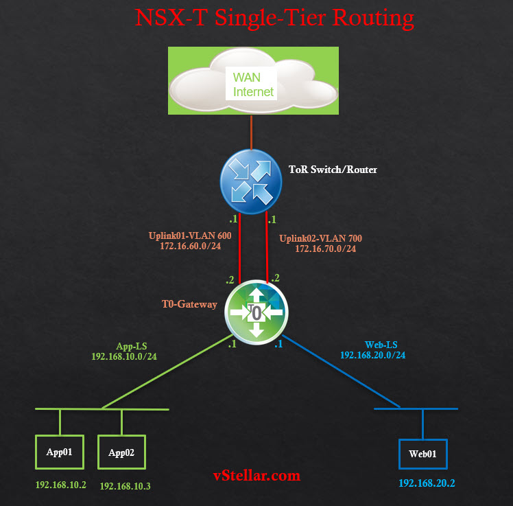
In single-tier routing, NSX-T workload segments connect directly to a Tier-0 gateway. It’s the tier-0 gateway that provides both distributed routing and centralized routing, along with other services such as NAT, DHCP, load balancers, and so on.
In this deployment model, both East-West & North-South routing is taken care of by the tier-0 gateway. There is no T1 gateway in a single-tier deployment.
The diagram is a representation of how single-tier routing looks. In this architecture:
1: There are 2 workload segments (App-LS & Web-LS), and both segments connect directly to the tier-0 gateway.
2: Tier-0 is connected to the physical router via 2 uplinks (both in separate VLANs)
3: The upstream router is then connected to the WAN network.
To achieve this architecture, I have deployed a T0 gateway in my lab. The Tier-0 gateway is BGP peering with the upstream router. Please see this post for instructions on deploying T0 & configuring BGP.
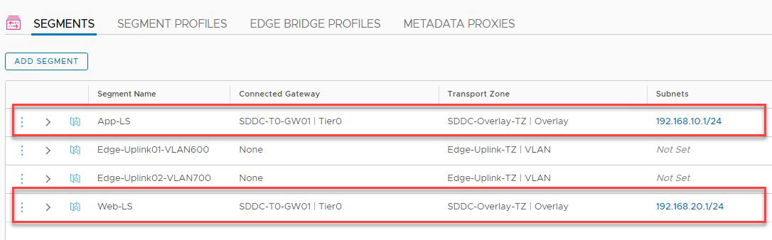
I also have 2 overlay segments created and attached directly to the Tier-0 gateway.
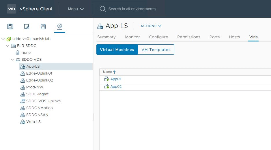
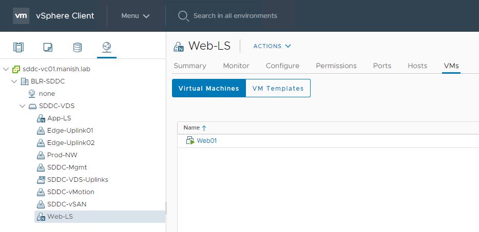
I have a couple of VMs connected to App-LS and one VM connected to Web-LS. The default gateways of both the VMs are pointing to the .1 IP of their respective subnets.
East-West Routing Verification
Let’s connect to the VMS and verify whether or not east-west routing is working.
From the App01 VM, I tried pinging its default gateway, the App02 VM, which is on the same segment, and the web01 VM, which is on a different segment, and got ping results for all 3 tests.

Test results from the App02 VM.
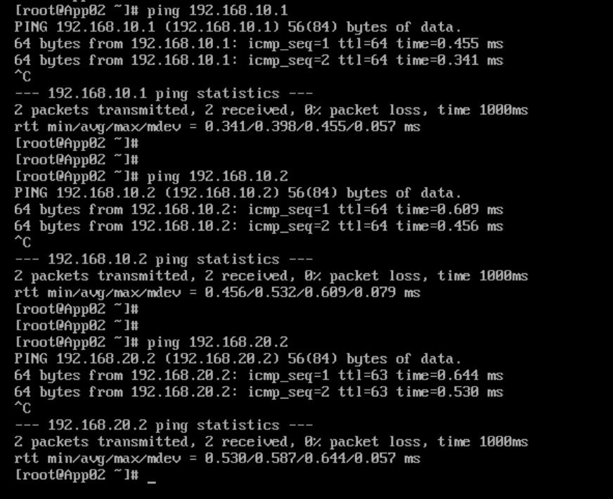
Test results from the Web01 VM.

The above test indicates that east-west routing is working fine between the app-ls and web-ls segments.
North-South Routing Verification
Let’s test north-south routing for the app and web workload VMs.
From the App01 VM, I tried pinging google.com and one of the physical servers and got ping results for both tests.

I performed the same test for the App02 & Web01 VMs and got results as expected.


And the above tests verify that north-south routing is also working fine.
And that’s it for this post. In the next post, I will explain the multi-tier routing architecture.
I hope you enjoyed reading the post. Feel free to share this on social media if it is worth sharing.