
In my last post, I discussed single-tier routing architecture and demonstrated how the T0 gateway handles both East-West & North-South routing. In this post, I will explain the two-tier (aka multi-tier) routing architecture.
If you are new to NSX-T, I would recommend reading the previous blog post from my NSX-T 3.0 series to gain some understanding.
1: NSX-T Management & Control Plane Setup
3: Transport Zones & Transport Node Profiles
5: Configure Logical Routing in NSX-T
Let’s get started.
Introduction
Two-tier architecture is the most common deployment method in a production environment. It lays the foundation of multi-tenancy by separating the tier-0 gateway (provider construct) from the tier-1 gateway (tenant construct).
In a multi-tenant environment, it’s the service provider who deploys and configures the tier-0 gateway. Tenants are responsible for creating & managing their respective T1 gateways.
Logical Routing Connectivity
Let’s do a quick recap about the components of the T0 & T1 gateways and how they interact with each other.
The tier-0 gateway, when deployed, hosts DR & SR components. The DR component is responsible for handling East-West traffic, and the SR component takes care of the North-South traffic.
When the T1 gateway is created and attached to the edge cluster & T0 gateway, the DR component gets created on T1. When stateful services are enabled on T1, the SR component gets instantiated.
- The DR & SR components of the T0 & T1 gateway are connected via an internal (transit) link, which is backed by NSX-managed subnet 169.254.0.0/28.
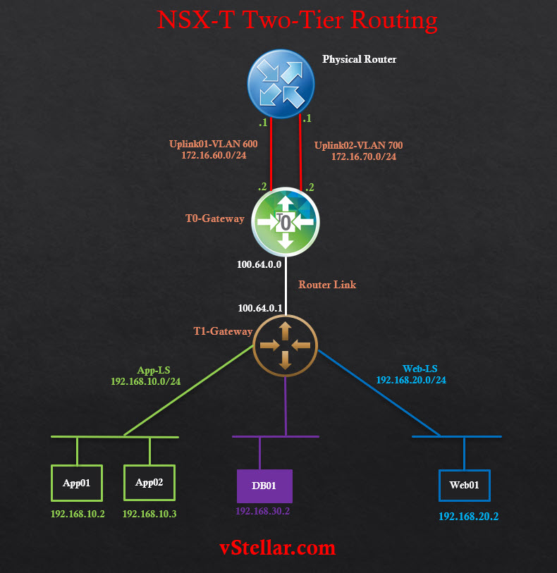
- The SR component of T1 gets attached to the DR component of T0 (when we connect T1 GW to T0) via another transit link called the router link, which is backed by NSX-managed subnet 100.64.0.0/16.
The tier-0 gateway connects to upstream routers via VLAN-backed uplinks. The T1 gateway has northbound connectivity with T0 over the Router Link. T1 also has downlinks to one or more L2 segments. Workloads are placed on these segments.
Since Router Link is created and managed by NSX-T, we don’t need to configure anything there to enable communication between T0 & T1. NSX-T takes care of configuring this automatically. However, we can restrict subnets from T0/T1 from being advertised to upstream routers via Route Filtering/Advertisement
The diagram is a logical representation of two-tier routing.
In this post, I am not covering the deployment steps of tier-0 & tier-1 gateways as I already covered them in earlier Post
Here is a quick tour of my lab.
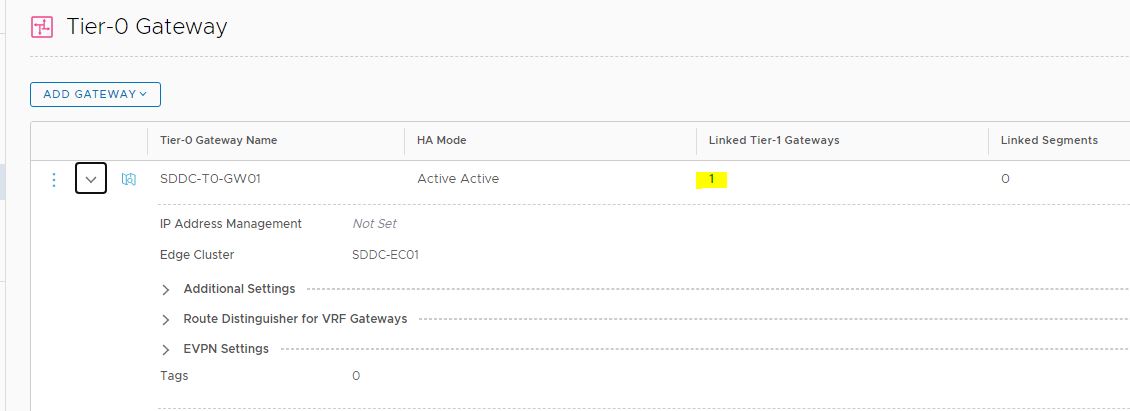
One tier-0 gateway is deployed and has one connected tier-1 gateway. There are no logical segments attached directly to T0.
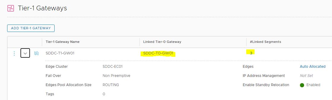
The tier-1 gateway is associated with an edge cluster. There are 3 logical segments connected to this tier-1 gateway.
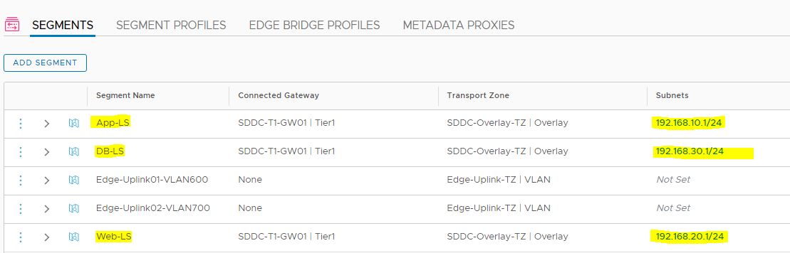
These segments are created in the overlay transport zone.
Routing Verification
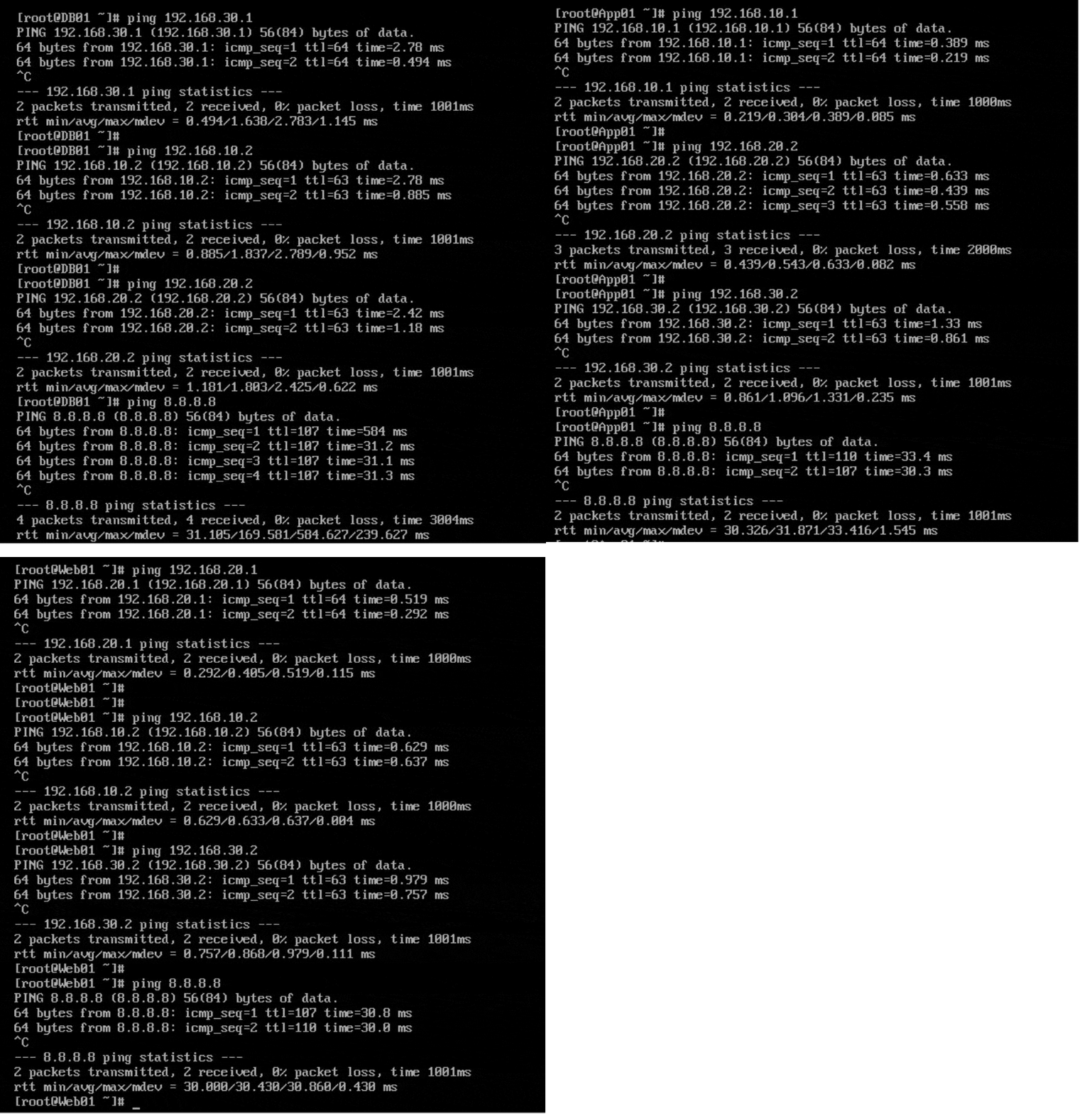
To verify routing, I connected to App01, Web01 & DB01 VMs one by one and performed the following test:
- Ping the default gateway
- pinged IPs of VMs that are on a different subnet than the one where the source VM is placed.
- pinged to the outside world.
All tests were successful, and thus I verified that both east-west & north-south routing are working fine.
And that’s it for this post.
I hope you enjoyed reading the post. Feel free to share this on social media if it is worth sharing.