
In my last post, I explained Egress/Ingress packet flow in a single-tier routing topology where logical segments are attached directly to the T0 gateway.
In this article, I will explain the same for a multi-tier routing topology in NSX-T.
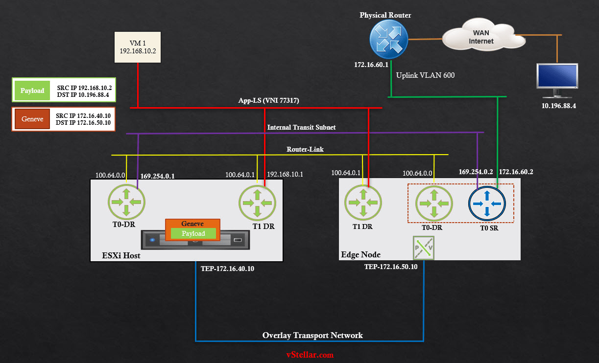
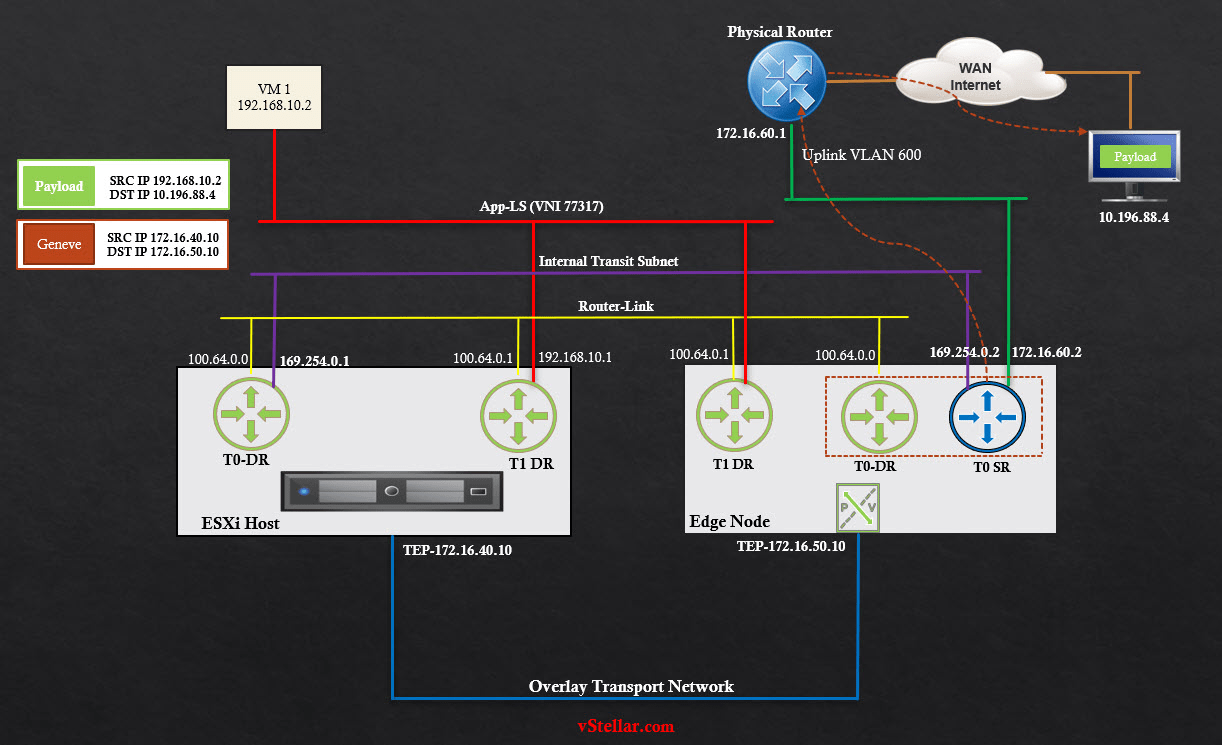
Here is the topology that I have used in my lab.
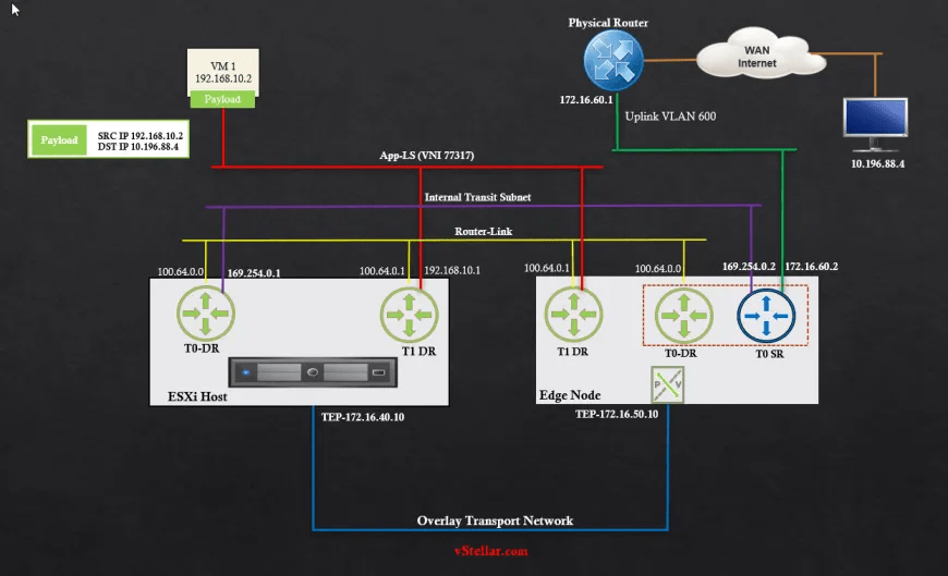
Egress to Physical Network
Scenario: VM 1 with IP 192.168.10.2 is connected to the logical segment App-LS and wants to communicate with a VM with IP 10.196.88.2, which is reachable on the physical network.
Step 1: VM 1 sends a packet to its default gateway (192.168.10.1), which is the LIF IP on T1-DR.
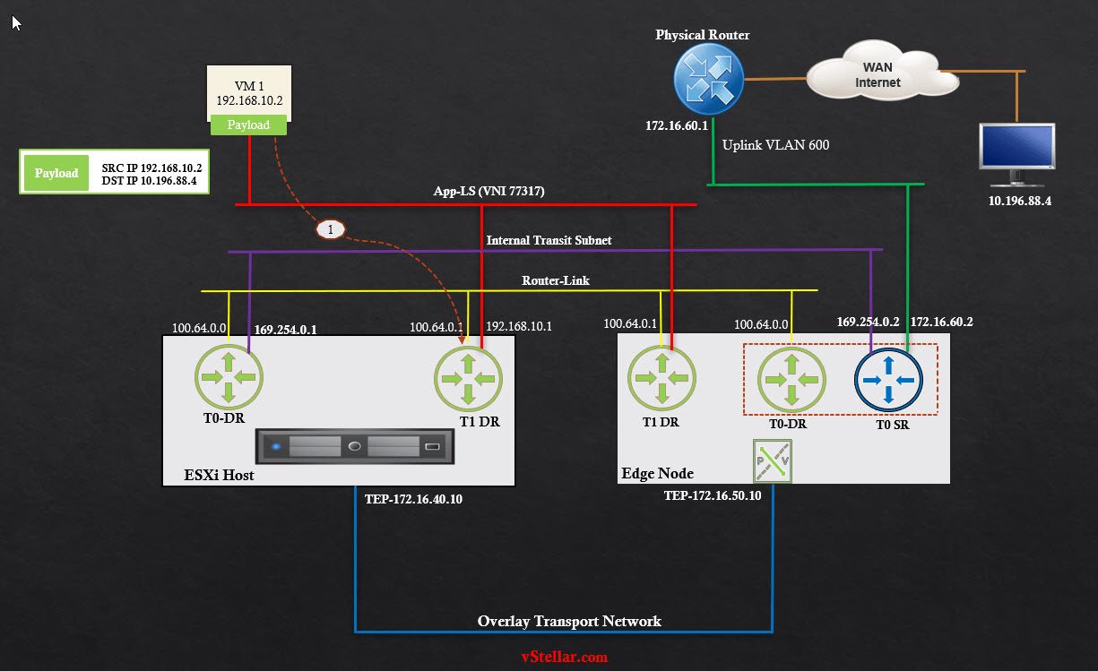
Step 2: T1 DR checks its forwarding table to make a routing decision. Since the route to network 10.196.88.x doesn’t exist in the forwarding table, T1-DR sends the packet to its default gateway (100.64.0.0), which is the DR instance of Tier-0 on the same hypervisor.
Step 3: The packet is sent to the T0 DR instance over the internal segment (Router-Link).
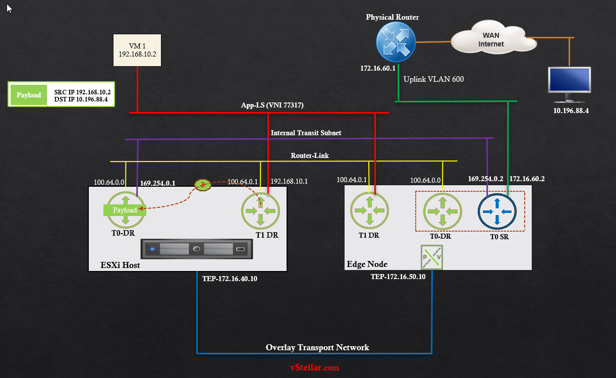
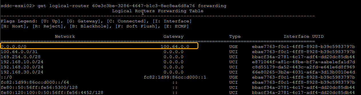
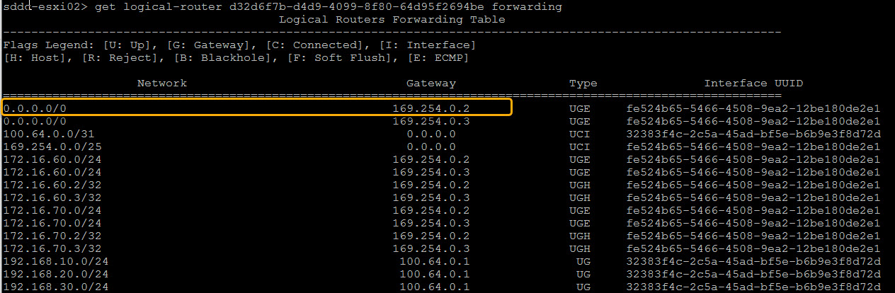
Step 4: On receiving a packet from T1-DR, the T0 DR checks its forwarding table to make a routing decision. Since there is no route to the 10.196.88.x network, the packet is sent to the default gateway (169.254.0.2), which is the T0-SR component on the edge node.
Step 5: To send the packet from the hypervisor to the edge node, the packet is encapsulated with a Geneve header.
Step 6: The encapsulated packet is sent to the edge node across the overlay tunnel.
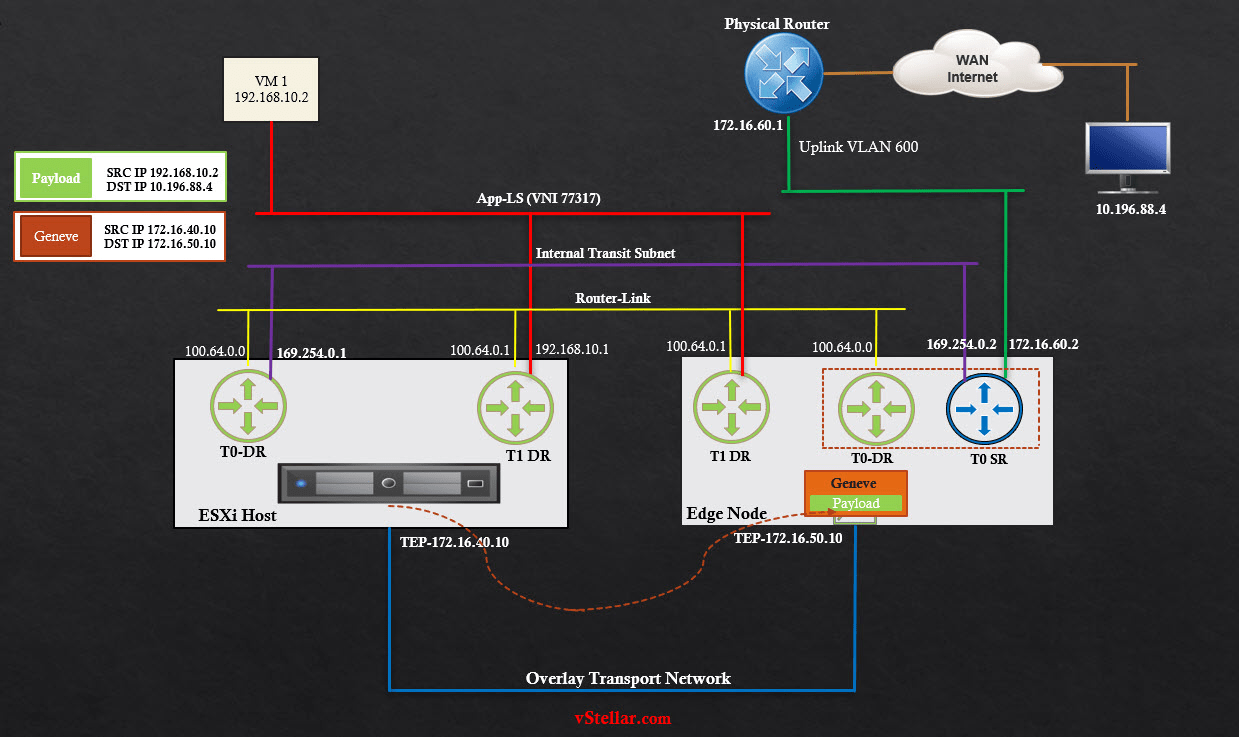
Step 7: The edge node decapsulates the packet and sends it to its T0 SR instance.
Step 8: On receiving the decapsulated packet, T0-SR checks its routing table and discovers it has a route to the 10.196.88.0/24 network over the uplink segment.
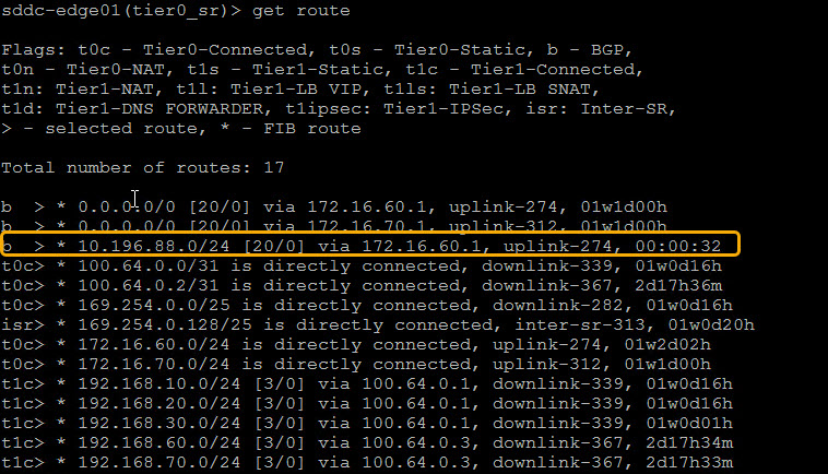
Step 9: T0-SR sends the packet to the upstream physical router, which then routes it to the destination VM.
Ingress From Physical Network
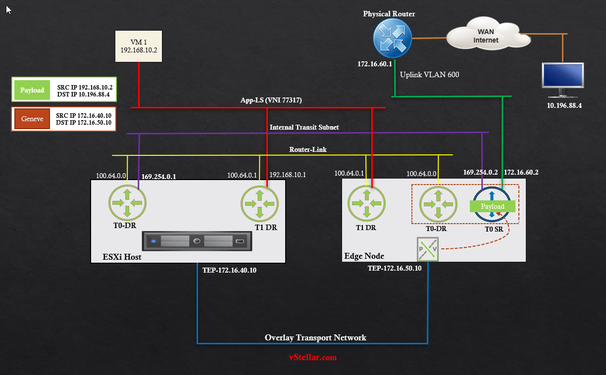
Step 1: Source VM (10.196.88.4) sends the return packet to its default gateway, which is an IP on the physical router. The router checks its routing table and determines it has a route to the 192.168.10.0/24 network via 172.16.60.2 (edge uplink).
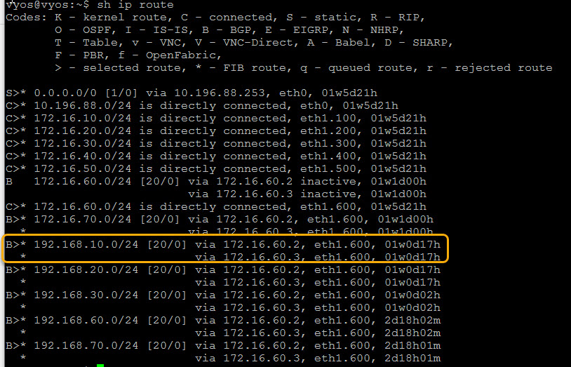
The packet is then routed to the edge node (T0-SR).

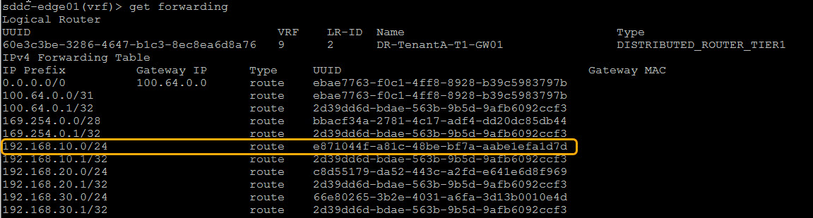
Step 2: T0-SR checks its forwarding table and determines it has a route to the 192.168.10.0/24 network via 100.64.0.1, which is the interface IP of T1-DR.

Step 3: The packet is then sent to the T1 DR instance on the edge node through the internal segment.

Step 4: T1-DR checks its forwarding table to make a routing decision. A route is directly connected to the 192.168.10.0/24 network. The packet is sent to the hypervisor host.
Step 5: The packet is encapsulated with Geneve headers before it is sent to the hypervisor host.

Step 6: The encapsulated packet is sent to the hypervisor via the overlay transport network.

Step 7: The ESXi decapsulates the packet and routes it to its destination VM.

And this concludes the N-S packet walk in the NSX-T multi-tier routing architecture.
I hope you enjoyed reading the post. Feel free to share this on social media if it is worth sharing.