

In my last post, I explained Egress/Ingress packet flow in a single-tier routing topology where logical segments are attached directly to T0 gateway.
In this article I will explain the same for a multi-tier routing topology in NSX-T.
Here is the topology which I have used in my lab.

Egress to Physical Network
Scenario: VM 1 with IP 192.168.10.2 is connected to logical segment App-LS and wants to communicate with a VM with IP 10.196.88.2 which is out there on physical network.
Step 1: VM 1 sends packet to its default gateway (192.168.10.1) which is LIF IP on T1-DR.

Step 2: T1 DR checks its forwarding table to make a routing decision. Since route to network 10.196.88.x doesn’t exist in forwarding table, T1-DR sends the packet to its default gateway (100.64.0.0) which is the DR instance of Tier-0 on the same hypervisor.

Step 3: The packet is sent to the T0 DR instance over internal segment (Router-Link).

Step 4: On receiving packet from T1-DR, T0 DR checks its forwarding table to make a routing decision. Since there is no route to 10.196.88.x network, the packet is sent to the default gateway (169.254.0.2), which is the T0-SR component on the edge node.

Step 5: To send the packet from the hypervisor to the edge node, the packet is encapsulated with a Geneve header.

Step 6: The encapsulated packet is sent to the edge node across the overlay tunnel.

Step 7: The edge node decapsulates the packet and sends it to its T0 SR instance.

Step 8: On recieving the decapsulated packet, T0-SR checks its routing table and discovers it has a route for the 10.196.88.0/24 network over the uplink segment.

Step 9: T0-SR sends the packet to upstream physical router, which in turn routes the packet to destination vm.

Ingress From Physical Network
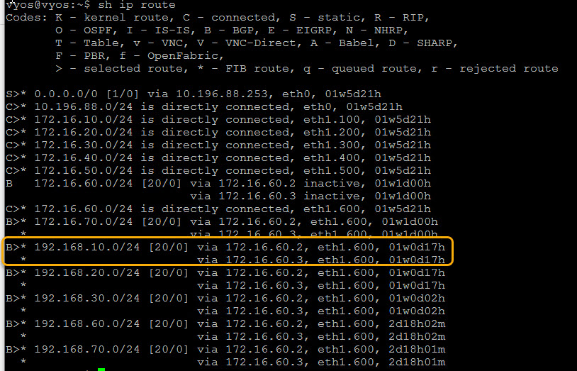
Step 1: Source VM (10.196.88.4) sends the return packet to its default gateway from where the packet is sent to the physical Router. The Router checks its routing table and determines it has a route to 192.168.10.0/24 network via 172.16.60.2 (edge uplink).
Packet is then routed to the edge node (T0-SR).

Step 2: T0-SR checks its forwarding table and determines it has a route to 192.168.10.0/24 network via 100.64.0.1 which is the interface IP of T1-DR.

Step 3: The packet is then sent to the T1 DR instance on the edge node through internal segment.

Step 4: T1-DR checks its forwarding table to make a routing decision. A route is directly connected to the 192.168.10.0/24 network. The packet is sent to the hypervisor host.

Step 5: Packet is encapsulated with Geneve headers before sending it to hypervisor host.

Step 6: The encapsulated packet is sent to the hypervisor via the overlay transport network.

Step 7: Hypervisor host decapsulates the packet and routes it to its destination vm.

And this concludes the N-S packet walk in NSX-T multi-tier routing architecture.
I hope you enjoyed reading the post. Feel free to share this on social media if it is worth sharing 🙂