
In last post of NSX-T series, I demonstrated East-West packet flow and discussed various cases around that. In this post I will explain how packets are forwarded in case of northbound/southbound traffic.
Before you start reading this article, please ensure you have fair understanding of NSX-T routing architecture and how SR & DR component of logical router work together. Also knowledge of TEP/MAC/ARP table formation is handy when trying out packet flow in lab/prod.
Here is the lab topology that I am going to use to demonstrate N-S packet walk.
Note: Below topology is single-tier routing topology.

Egress to Physical Network
Here is how a packet traverse when VM 1 which is on App-LS logical segment tries to communicate with VM 2 which is out there on physical network.
Step 1: VM 1 sends layer 2 packet to its default gateway (192.168.10.1) which is a LIF on DR component on hypervisor node.
Step 2: DR component checks its forwarding table to see if it has a route to 10.196.88.2 subnet. Since the route to 10.196.88.x subnet doesn’t exist in forwarding table, DR have to send the packet to its default gw 169.254.0.2, which is the SR component on edge node.

Step 3: Before sending the packet to edge node, DR component on hypervisor encapsulate the packet with a Geneve header.

Step 4: The encapsulated packet is sent to the edge node via TEP tunnel (overlay transport network)

Step 5: On receiving the packet, edge node decapsulates the packet and sends it to its SR component. SR component checks its routing table and finds out it has a route to 10.196.88.x network (learnt via bgp) over uplink segment.
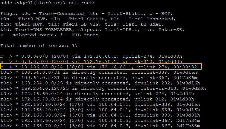
Step 6: SR component sends the packet to its upstream physical router, which routes the packet to its destination vm (10.196.88.4)

Ingress from Physical Network
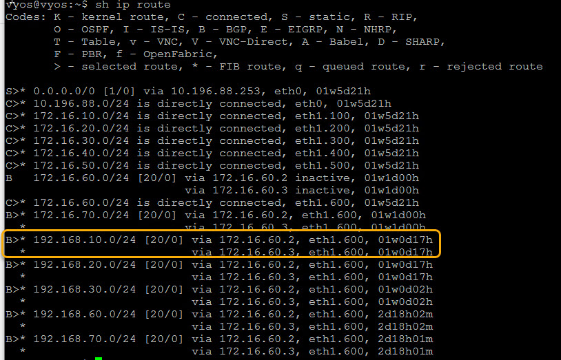
Step 1: Source VM (10.196.88.4) sends the return packet to its default gateway from where the packet is sent to the physical Router. The Router checks its routing table and determines it has a route to 192.168.10.0/24 network via 172.16.60.2 (edge uplink). Packet is then routed to the edge node.
Step 2: SR component checks its routing table and find that it has a directly connected route to 192.168.10.0/24 via interface downlink-412.

Downlink-412 is nothing but an interface on DR component.
|
1 2 3 4 5 6 7 8 9 10 11 |
sddc-edge01(vrf)> get interfaces Logical Router UUID VRF Name Type 60e3c3be-3286-4647-b1c3-8ec8ea6d8a76 5 DR-TenantA-T1-GW01 DISTRIBUTED_ROUTER_TIER1 Interface : f0996aef-5365-410e-b7dc-8486afbe9dc3 Name : infra-App-LS-dlrp Internal name : downlink-412 Mode : lif Port-type : downlink IP/Mask : 192.168.10.1/24 |
The packet will sent to the remote host by using the DR interface.
Step 3: Before sending the packet from edge node to the hypervisor, it is encapsulated with a Geneve header.

Step 4: The encapsulated packet is sent over the overlay network.

Step 5: The transport node then decapsulates the packet and routes it to its destination vm (192.168.10.2)

And this concludes the N-S packet walk in NSX-T single-tier routing architecture.
In next post I will explain N-S packet walk in Multi-Tier routing topology.
I hope you enjoyed reading the post. Feel free to share this on social media if it is worth sharing 🙂