
In this post, I will be talking about the Layer 2 bridging functionality of NSX-T and discussing use cases and design considerations when planning to implement this feature. Let’s get started.
NSX-T supports L2 bridging between overlay logical segments and VLAN-backed networks. When workloads connected to the NSX-T overlay segment require L2 connectivity to either VLAN-connected workloads or need to reach a physical device (such as a physical GW, LB, or Firewall), the NSX-T Layer 2 bridge can be leveraged.
Use Cases of Layer 2 Bridging
A few of the use cases that come to the top of my mind are the following:
1: Migrating workloads connected to VLAN port groups to NSX-T overlay segments: Customers who are looking to migrate workloads from legacy vSphere infrastructure to SDDC can leverage Layer 2 bridging to seamlessly move their workloads.
When planning for migrations, some of the challenges associated with migrations are Re-IP of workloads, migrating firewall rules, NAT rules, etc. There are situations where re-IP is not feasible because of application dependencies. With L2 bridging, you don’t have to worry about this stuff at all.
2: Migrate from NSX-V to NSX-T: NSX-V is phasing out slowly, and there are a lot of customers who are still using NSX-V in their infrastructure. It’s possible to migrate workloads connected to NSX-V logical switches to NSX-T overlay segments.
3: Leveraging the NSX-T Gateway Firewall: VLAN-backed workloads can leverage the NSX security services by having the traffic routed over a T1 or T0 Gateway.
It’s time to jump into the lab and see things in action.
Before configuring the L2 Bridge, let’s discuss my lab topology, which is shown below.

The left-hand side of the diagram shows VLAN-based networks. Three VLANs are connected to the top-of-rack switch. VLAN 201 hosts the application VM, VLAN 202 is for web VMs, and VLAN 203 is for database VMs. Subnets corresponding to these VLANs are marked as well in the diagram.
The right-hand side of the diagram shows NSX-T overlay networks. Subnets corresponding to overlay segments have been matched with VLAN-based networks. The only difference between the two is the default gateway IP. For a VLAN-backed network, it’s .1, and for overlay segments, the default gateway is .253.
Once the L2 Bridge is configured, I will demonstrate the migration of the three-tier application to the NSX-T environment without making any configuration changes to the App, Web & DB virtual machines.
Now it’s time to jump into the lab and see things in action.
Step 1: Create Trunk Portgroup in vSphere
Create a new trunk port group in vSphere, allowing the VLANs that you are planning to bridge with the overlay.

Set Promiscuous mode and Forged transmits on this port group to Accept.

Set the teaming policy for this port group to explicit failover order, choosing one uplink as active and the other as standby.

Step 2: Enable Reverse Path Filter on the ESXi host
Run the following command to enable the reverse filter on the ESXi host where the Edge VM is running:
|
1 |
# esxcli system settings advanced set -o /Net/ReversePathFwdCheckPromisc -i 1 |
After running the above command, disable/enable promiscuous mode on the trunk port group so that the reverse filter becomes active.
Step 3: Create a VLAN Transport Zone for Bridging
Create a new VLAN Transport Zone for edge bridging. This transport zone will be added to Edge VMs in the next step.

Step 4: Associate Edge Nodes with Bridge TZ
Bridging between the physical and virtual networks is performed via edge nodes, so we must add edges to the bridge transport zone, which we just created.
To associate the bridge transport zone with Edge VMS, edit the edge VM properties under System > Configuration > Fabric > Nodes > Edge Transport Nodes.
Click on Add Switch to add a new N-VDS on the edge.

Provide a name for the N-VDS and add the Bridge TZ here.
For the uplink profile, select nsx-edge-single-uplink-profile, and under uplink mapping, map the edge uplink to the trunk port group created in Step 1.

Step 5: Create Edge Bridge Profile
The Edge bridge profile is the configuration item that ties together the Edge bridge with the overlay segments, which will take part in bridging.
To create an Edge Bridge Profile, navigate to Networking > Connectivity > Segments > Edge Bridge Profiles and click on Add Edge Bridge Profile.

Provide a name for the profile and specify the primary & backup edge nodes. Make sure failover is set to preemptive.
Also, select the edge cluster with which this profile will be associated.

Step 6: Create Overlay Segments for Bridging
Create necessary overlay segments with the same subnets that exist for VLAN-connected workloads. Make sure the default gateway for the chosen subnet is different from the gateway of the VLAN-based port groups.

Step 7: Associate Overlay Segment with the Edge Bridge Profile
To associate an overlay segment with a bridge profile, edit the settings of the segment and click on Set under Edge Bridges.

Click on the Add Edge Bridge and select the profile created in Step 5. Also, select the bridge transport zone that you created earlier.
Specify the VNI to VLAN mapping: This is where we map an overlay segment with the VLAN that exists on the physical network. Since my App-LS corresponds to VLAN 201, I have entered the same under VLAN.

And that’s it for the bridge configuration. Now it’s time to test the setup.
Test L2 Bridge
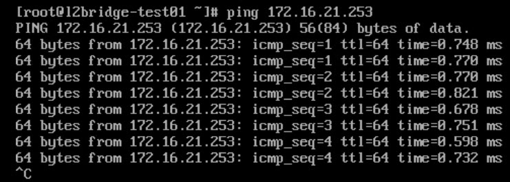
In vSphere, I have 2 VMs, namely L2-Bridge-Test01 & L2-Bridge-Test02, connected on networks VLAN-201 & App-LS (overlay), respectively.


From the L2-Bridge-Test01 VM, I pinged the 172.16.21.253 IP, which is the default gateway of the overlay segment, and the ping test passed.
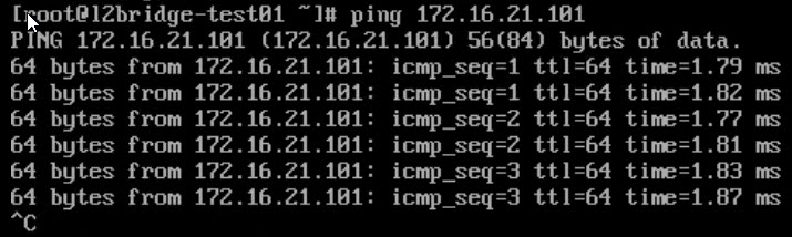
Then I pinged the IP of the L2-Bridge-Test02 VM, and the ping test passed again.
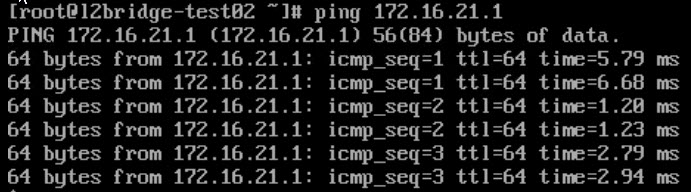
From the L2-Bridge-Test02 VM, I pinged the 172.16.21.1 IP, which is the default gateway of the VLAN network and exists on my top-of-rack switch. Got a successful ping response.
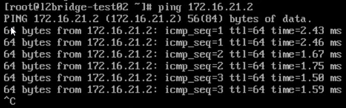
Ping responded for L2-Bridge-Test01 as well.
As the next step of testing, the L2-Bridge-Test01 VM was migrated from the VLAN-201 network to the App-LS network with continuous ping.
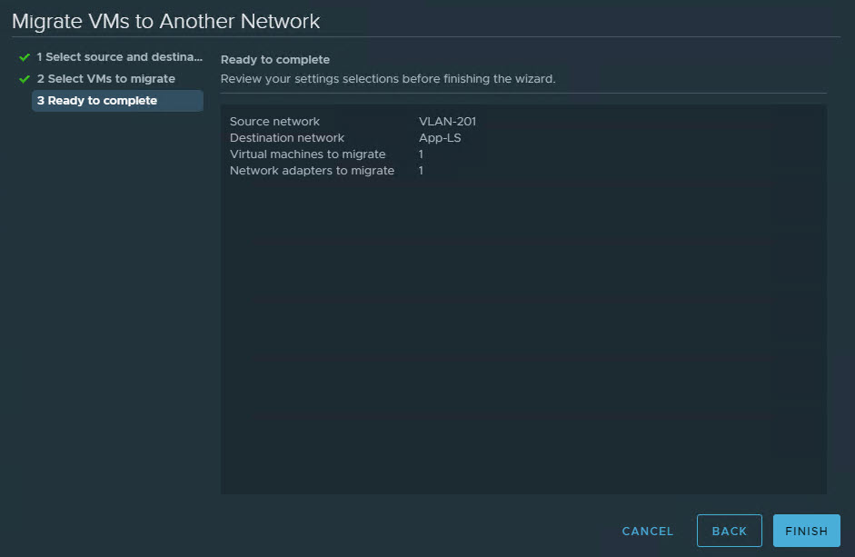
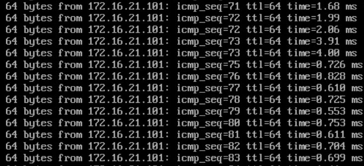
Not a single ping was missed. Although latency did increase after icmp_seq 73 (when cutover happened)
Once the VM migration from the VLAN network to the overlay network completes, you must change the VM default gateway to the overlay segment gateway address.
I hope you enjoyed reading this post. Feel free to share this on social media if it is worth sharing. 🙂