In the last post of this series, we created logical switches and established communication between the App and Web VMs, which were on the same subnet and connected to the same logical switch.
In this post, we will learn about logical routing.
If you are not following along with this series, then I recommend reading earlier posts of this series from the links below:
4: NSX Controllers Automated Deployment
5: NSX Controllers Manual Deployment
6: Prepare Esxi host to form NSX-T Fabric
8: Configuring Transport Zone and Transport Nodes
9: Creating Logical Switches and Testing Connectivity
Optimal routing is one of the biggest challenges in any data center, and NSX revolutionized the way networking is used in infrastructure.
NSX-v offered distributed routing to SDDC, and because of this, routing between different subnets on an ESXi hypervisor can be done in the kernel, and traffic never has to leave the hypervisor, thus eliminating the traffic hairpinning problems.
Logical routing drastically reduced the East-West traffic that used to flow in a data center without NSX. With NSX-T, logical routing functionality is extended to a multi-hypervisor and multi-cloud environment.
Logical routing is provided by the logical router, which is deployed as an appliance, and it handles east-west routing between different subnets. A logical router has 2 components:
- Distributed component: It runs as a kernel module in the hypervisor
- Centralized Component: This component takes care of centralized functions like NAT, DHCP, LB, etc, and provides connectivity to physical infrastructure.
In NSX-T, we have two types of logical routers:
- Tier-0 Logical Router: A Tier 0 router is used to connect NSX networking with traditional physical networking. A Tier 0 router forwards layer 3 IP packets and typically peers with a traditional physical router using BGP or can use static routing.
- Tier-1 Logical Router: A tier-1 logical router is often used for tenants, users, and applications. Tier-1 logical routers have downlink ports to connect to NSX-T logical switches and uplink ports to connect to NSX-T tier-0 logical routers.
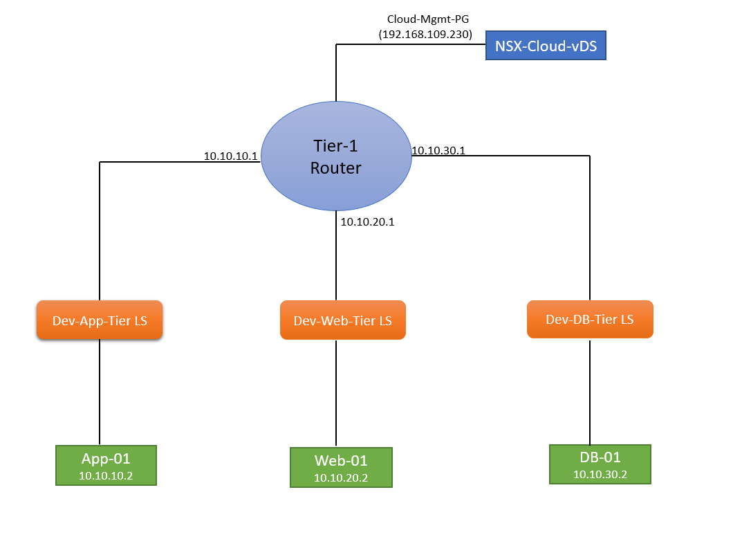
In my lab, I have a 3-tier application that consists of an App VM, a Web VM, and a DB VM, and they are on the following subnets:
- App-NW: 10.10.10.0/24
- Web-NW: 10.10.20.0/24
- DB-NW: 10.10.30.0/24
Here is how my lab topology looks
Let’s jump into the lab and deploy a Tier-1 router and try to establish communication between the 3-tier application.
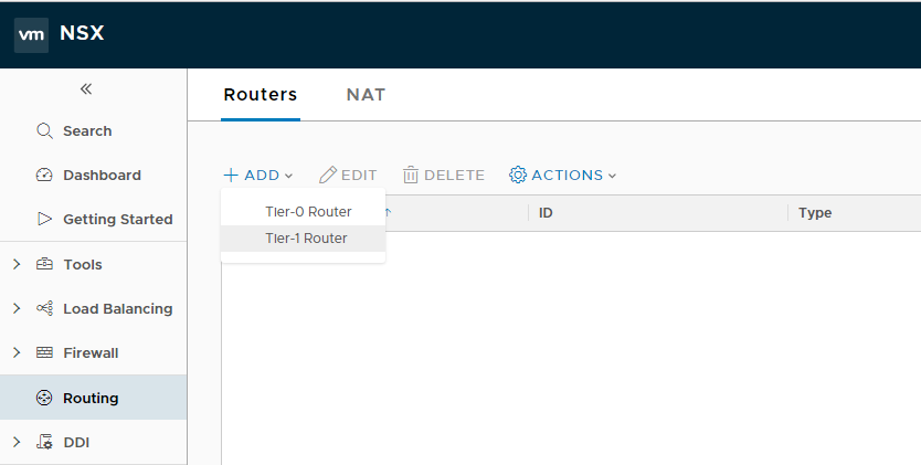
To deploy a logical router, login to NSX Manager and navigate to Home > Routing > Routers and click on the + Add button, and select Tier-1 Router.
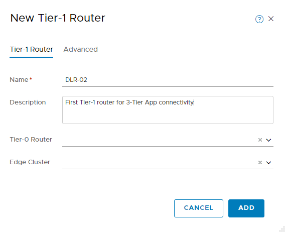
- Provide a name for the router and an optional description.
- Tier-0 Router: If you have any Tier-0 router in your environment to which this Tier-1 router should connect, then select it from the drop-down menu; otherwise, leave it blank.
- Edge Cluster: If the tier-1 logical router is going to be used for NAT configuration, it must be connected to an NSX Edge cluster. If you do not yet have any edge clusters configured, you can leave this field blank for now.
Hit the Add button to finish the wizard.
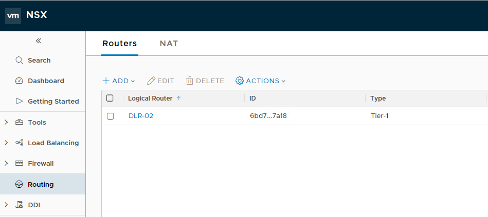
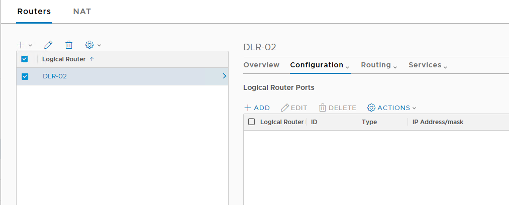
The newly deployed router will be visible in the list.
Double-click on the newly deployed router and go to the configuration tab to add interfaces to this router. Click on the + Add button to add new interfaces.
- Provide a name and an optional description for the interface.
- Select whether it will be an uplink or downlink interface.
- Select the logical switch to which this interface will connect.
- Select Attach to the new switch port and provide it a name.
- Supply the IP address that will be configured on this interface in CIDR format.
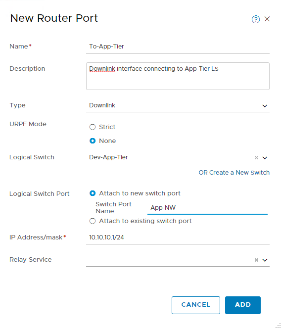
Repeat the process for other logical switches that you want to connect to the tier-1 router.
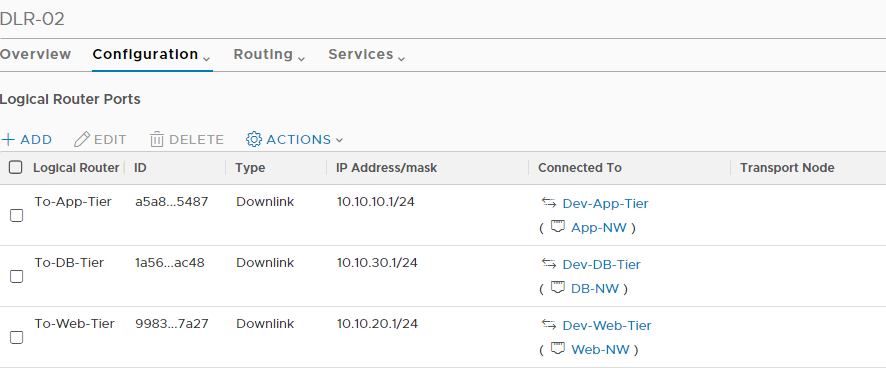
I added 3 logical switches to my Tier-1 router.
Now it’s time to test connectivity between VMs.
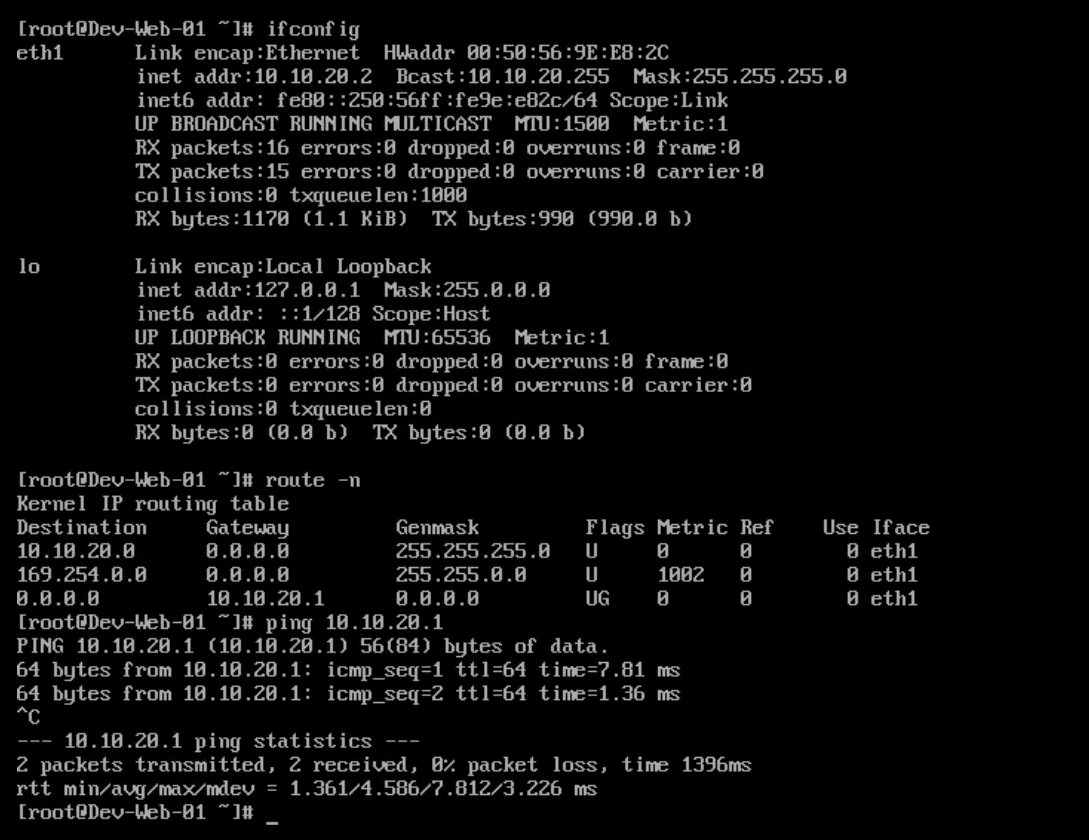
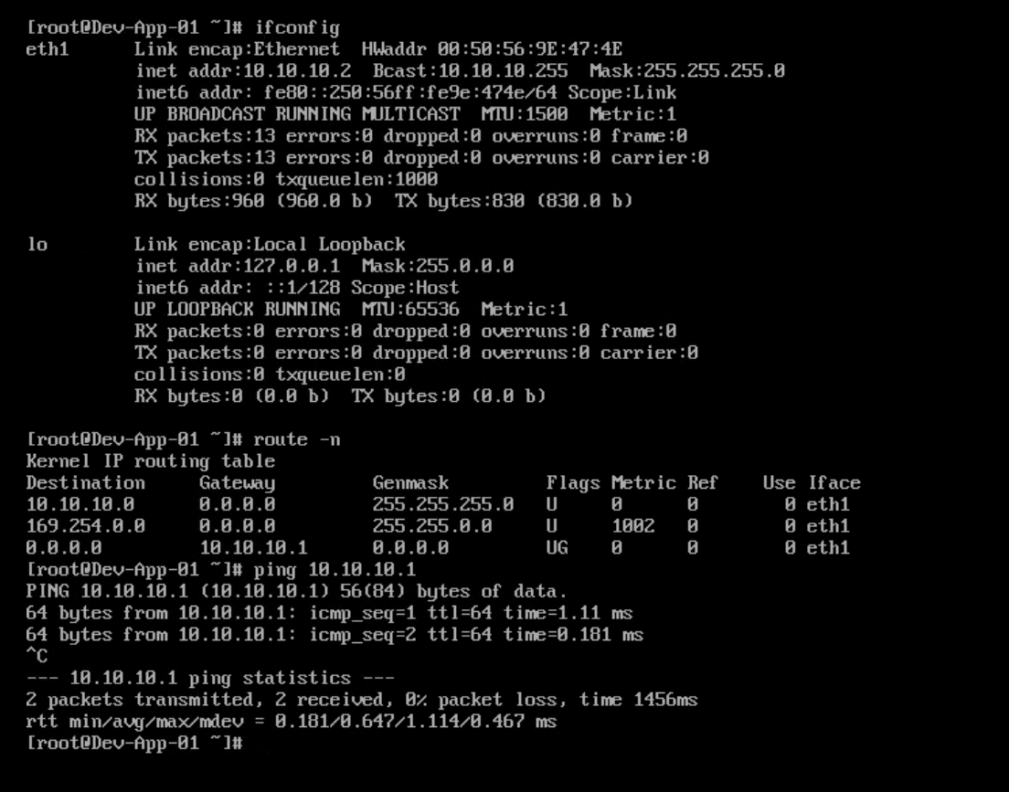
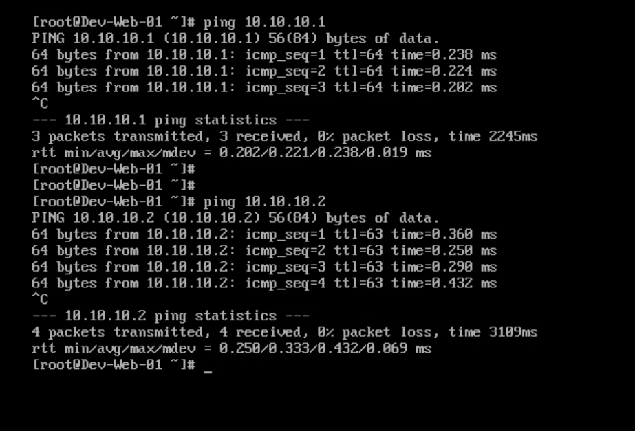
First, I verified that my Web-01 VM is on subnet 10.10.20.0/24 and the default gateway for this VM points to 10.10.20.1, which I configured on one of the interfaces of my Tier-1 router.
The VM can ping its default gateway.
I verified the same for my App-01 VM.
I initiated a ping from my App-01 VM to the Web-01 VM and got a ping response.
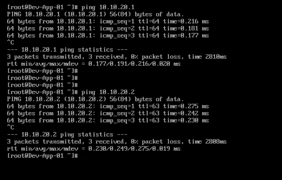
Then I pinged the App-01 VM from my Web-01 VM and got a ping response.
Test results from DB-01 VM are below.
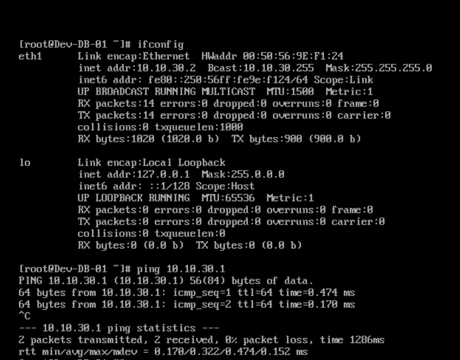
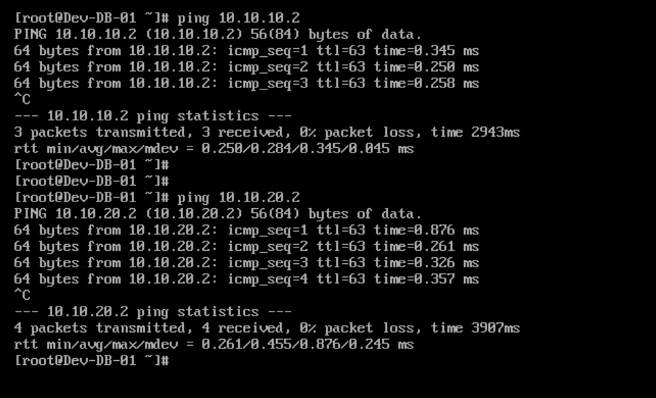
So now we have verified that all 3 VMs, which are on different subnets, can ping each other.
And that’s it for this post.
I hope you enjoyed reading this post. Feel free to share this on social media if it is worth sharing.