
Welcome to part 4 of the VCF-9 series. The previous post in this series discussed the networking models (VPC Networking and Segment Networking) and the key differences between them. In this post, I will discuss deploying NSX Edges through a built-in wizard in the vCenter UI.
If you are not following along, I encourage you to read the earlier parts of this series from the links below:
1: VCF-9 Architecture & Deployment Models
In previous VCF releases, NSX Edges were deployed through SDDC Manager using the UI/JSON. VCF-9 has introduced a newer way of deploying NSX Edge VMs, and the deployment can now be performed through vCenter UI to simplify the process, particularly for centralized external network connectivity. However, installation and configuration via the NSX Manager is still possible.
You will notice one change when deploying Edges through vCenter Server, i.e., instead of creating a tier-1 gateway, the wizard deploys a Transit Gateway. Transit gateways were introduced with VCF9 and are used to connect multiple VPCs in a project.
When you deploy edges from vCenter Server, you need to select the gateway type you want to deploy. The available modes for gateway connectivity are:
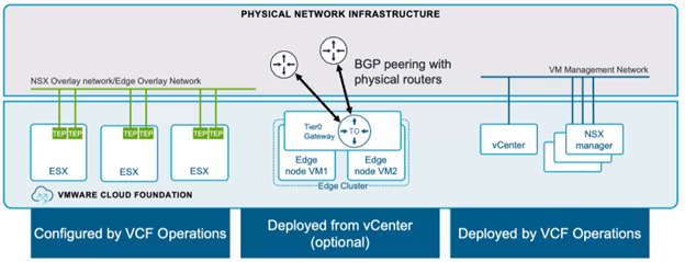
- Centralized Connectivity: In this mode, the Transit Gateway forwards traffic to a Tier-0 gateway, and a virtual router is instantiated on the NSX Edge VMs.
- Distributed Connectivity: In this mode, the Transit gateway can connect to physical infrastructure via an external VLAN network and doesn’t require any Edge VMs for forwarding traffic.
For centralized network connectivity, the wizard facilitates the deployment of NSX Edge VMs and configures a Tier-0 Gateway, enabling VPC connectivity to external networks through a centralized transit gateway architecture.

When setting up a centralized external connection for VPCs, the Transit Gateway SR component has the same span as the connected Tier-0 gateway SR. In other words, Transit Gateway SR is distributed across the same NSX Edge VMs that host the Tier-0 Gateway. Each TGW Service Router (SR) is tightly coupled with its corresponding Tier-0 SR.
This deployment can operate in either active/active or active/standby mode. The differences in the service supportability are outlined in the table below:
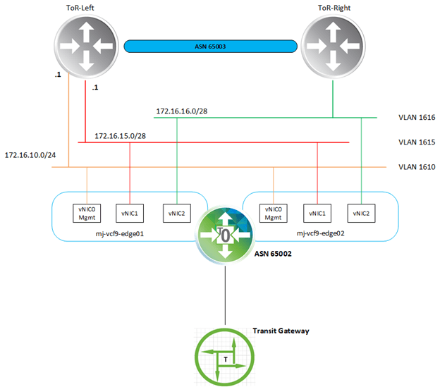
I am following the below design to deploy NSX edges in my lab.
An important note before we proceed to deploy NSX Edges:
If your ESXi host has only 2 pNICs, then for this configuration to work, the Edge TEP and the ESXi host TEP should be in a different VLAN and should be routable to each other via an external router.
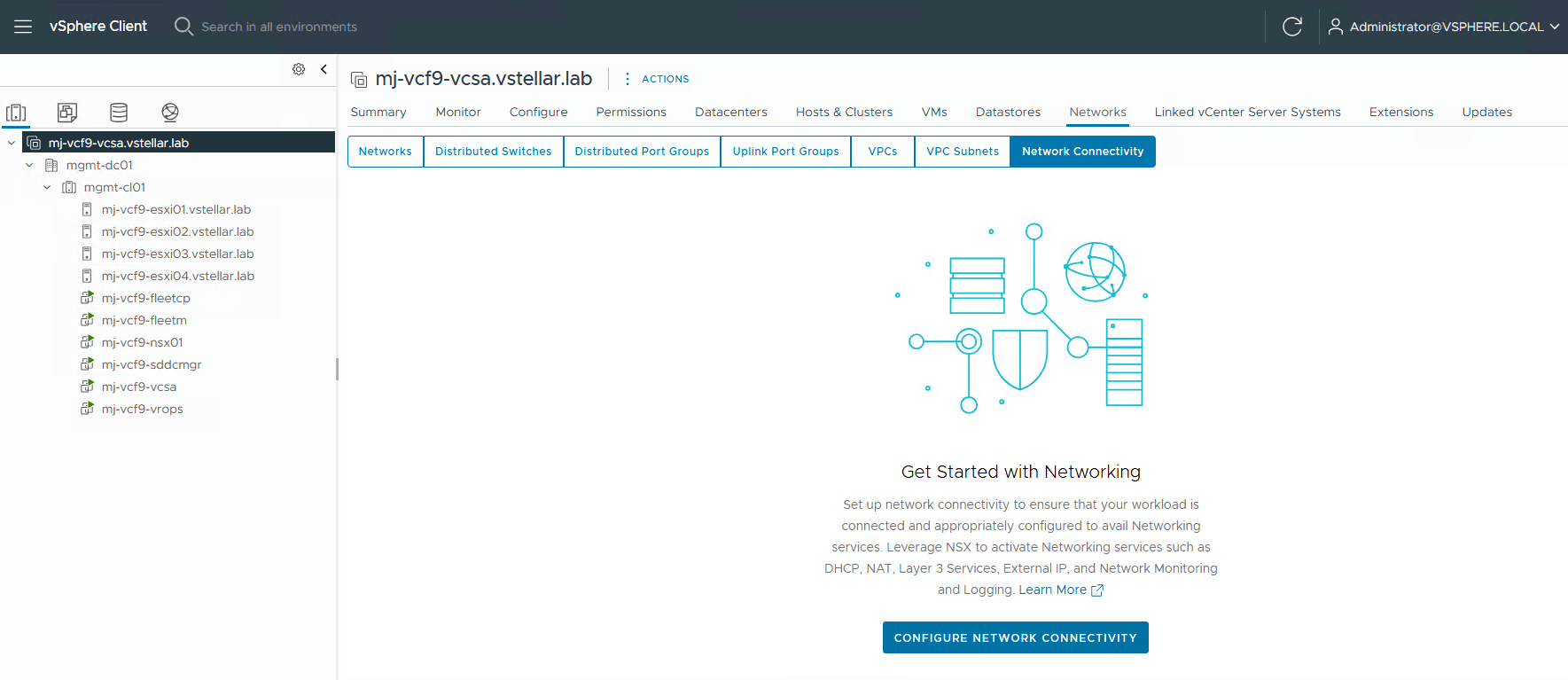
To deploy NSX Edges through vCenter, login to the vCenter UI and navigate to Networks > Network Connectivity, then click Configure Network Connectivity.
Select gateway type. For demonstration purposes, this post is focused on the centralized connectivity model.

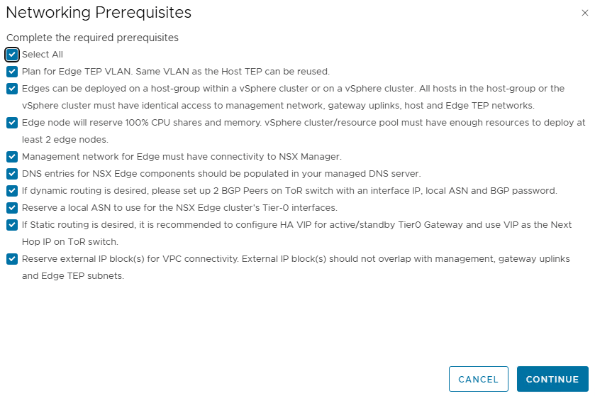
Ensure that you have met all networking prerequisites before proceeding with the deployment. This interface is similar to what the SDDC Manager UI shows when deploying Edges.
Specify the following configuration values for the edge cluster:
- Cluster name
- Edge VM size
- MTU for overlay traffic (this is auto-selected and is fetched from NSX Manager).
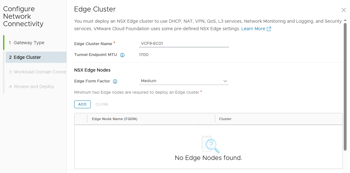
Click the Add button to add the Edge VMs to the Edge Cluster.
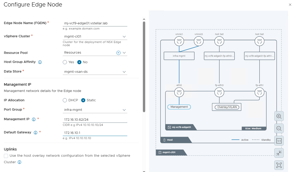
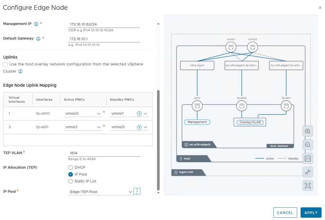
Configure the following values for the edge vm:
- Edge Node Name: This must match the FQDN configured in the DNS server for the NSX Edges.
- vSphere Cluster:
- Data Store:
- Management IP
- IP Allocation: Both DHCP and static are supported.
- Port Group: Select the infrastructure management port group where you have deployed vCenter, NSX Manager, etc.
- Management IP:
- Default Gateway:
Configure the edge node uplink teaming policy and specify the Edge TEP VLAN.
For TEP IPs, I am using an IP Pool. If a pool doesn’t exist, the wizard provides an option to create one on the fly.
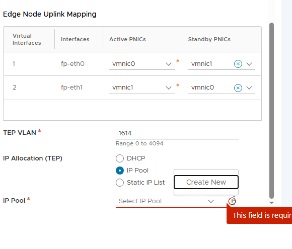
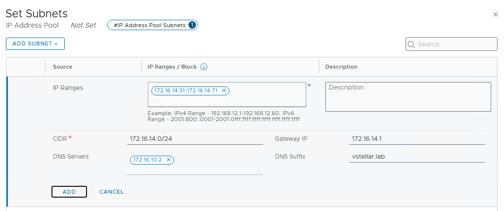
Specify the IP pool name and click on Set to define the TEP subnet.
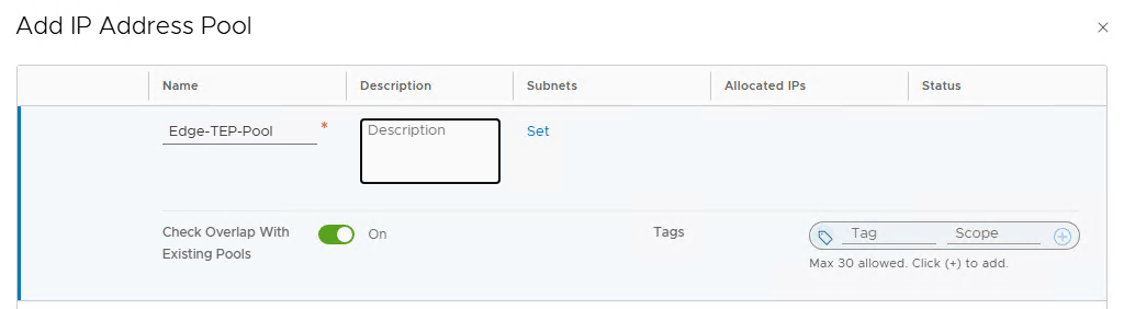
Provide the IP ranges, CIDR, gateway IP, etc.
Click Apply to save the configuration. The wizard draws a nice little architecture diagram for the edge connectivity.
Note: The wizard automatically creates two trunk port groups in vCenter for connecting the fp-eth0 and fp-eth1 interfaces of Edge with the dvpg.
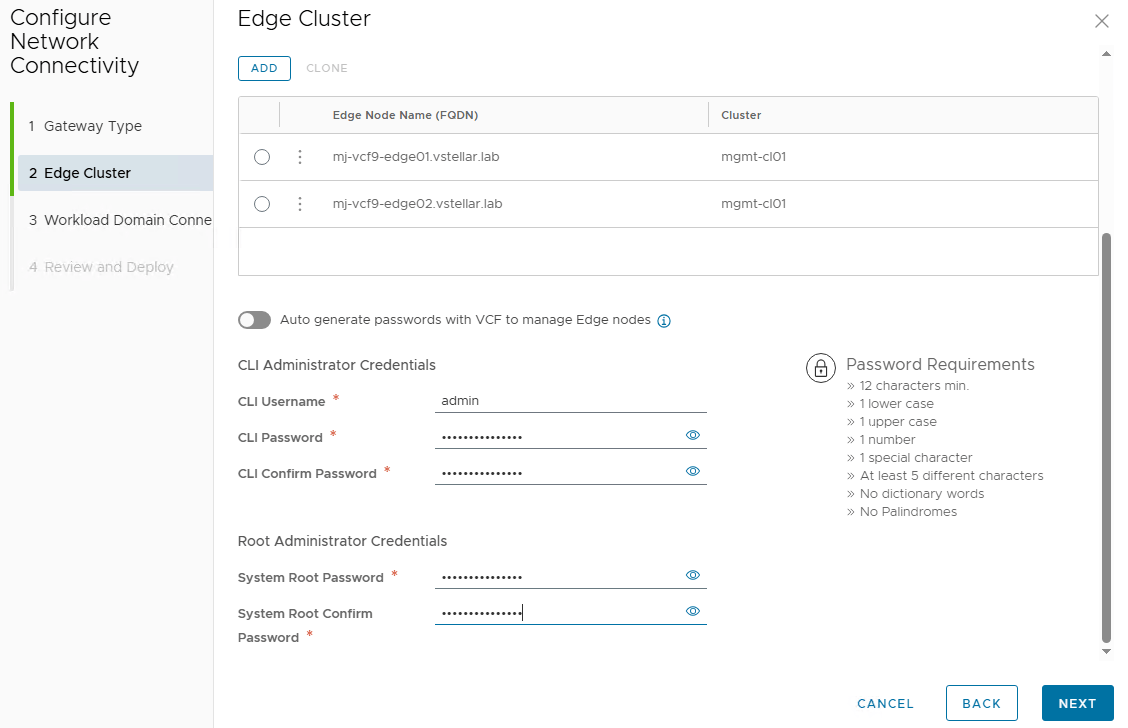
Repeat the process to add the second Edge VM in the edge cluster and configure the admin/audit and root credentials for the Edges.
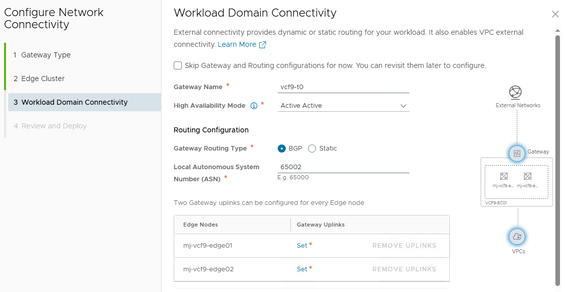
Tier-0 Gateway and BGP Configuration
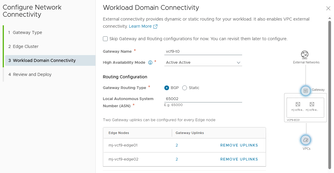
Provide a name for the Tier-0 gateway and select the HA mode.
Note: If you are planning to deploy VKS in your workload domain, set the “High Availability Mode” to Active/Standby.
Under Routing Configuration, select the routing type, and if BGP is selected, specify the local ASN for the Tier-0. Click on the set button to create the Tier-0 gateway interfaces.
Configure the tier-0 interfaces as per the VLANs configured in your infrastructure.
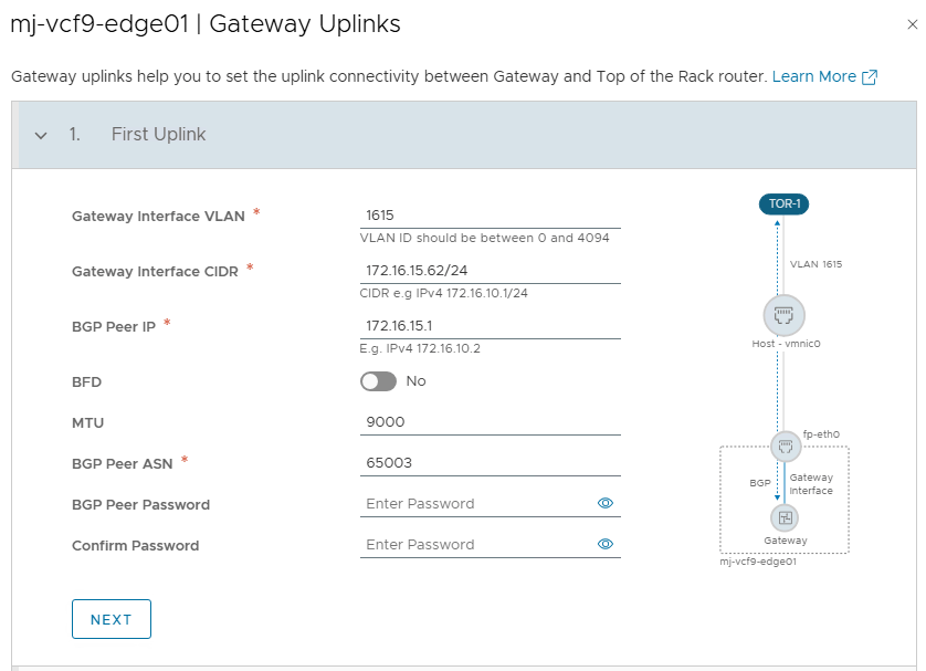
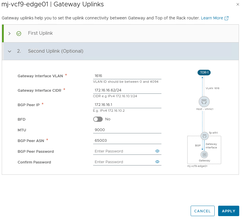
Configure the second interface for the first edge node.
Repeat the process for configuring interfaces on the second edge node.
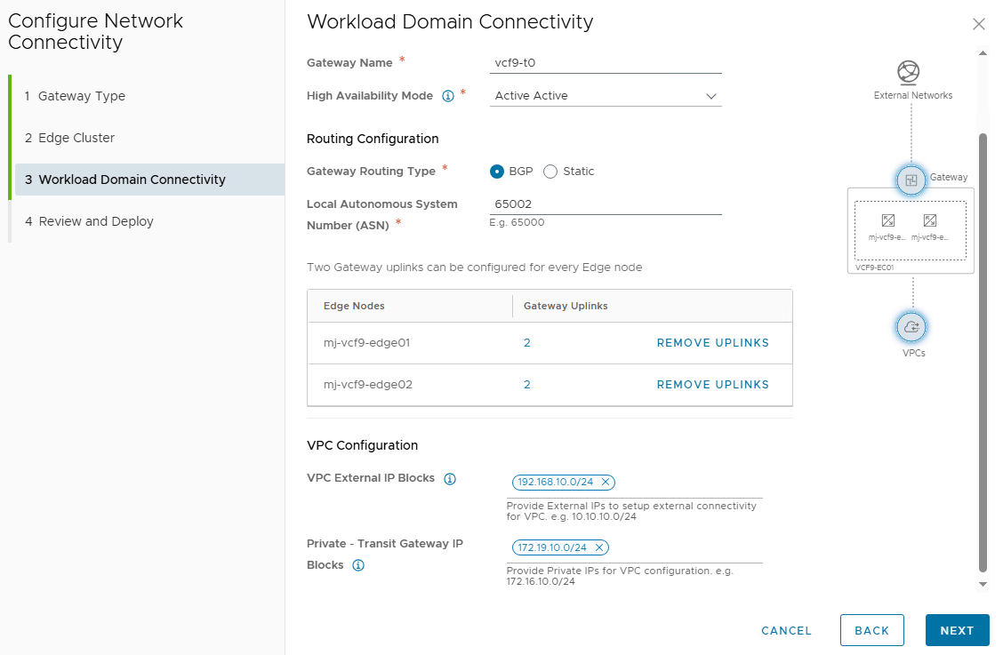
IP blocks for VPC
To enable networking within and outside VPCs, specific IP blocks must be pre-allocated at the project level where the transit gateway is defined. Two types of IP blocks are required:
- VPC external IP blocks: These are IP ranges owned by VCF and should not overlap with other ranges in the physical network. The Tier-0 gateway will advertise them to external routers via BGP.
- Private Transit Gateway IP Blocks: Used for Private Transit Gateway subnets. These IPs are not advertised to the northbound router and are scoped to the transit gateway’s project.
On the review and deploy page, you can review the configuration, and if everything looks good, click on the Deploy button to initiate the deployment.
The vCenter UI displays the Edge VMs deployment progress. The UI also displays the information about the IP blocks you created for the VPC external connectivity and the Transit gateway private IP block.
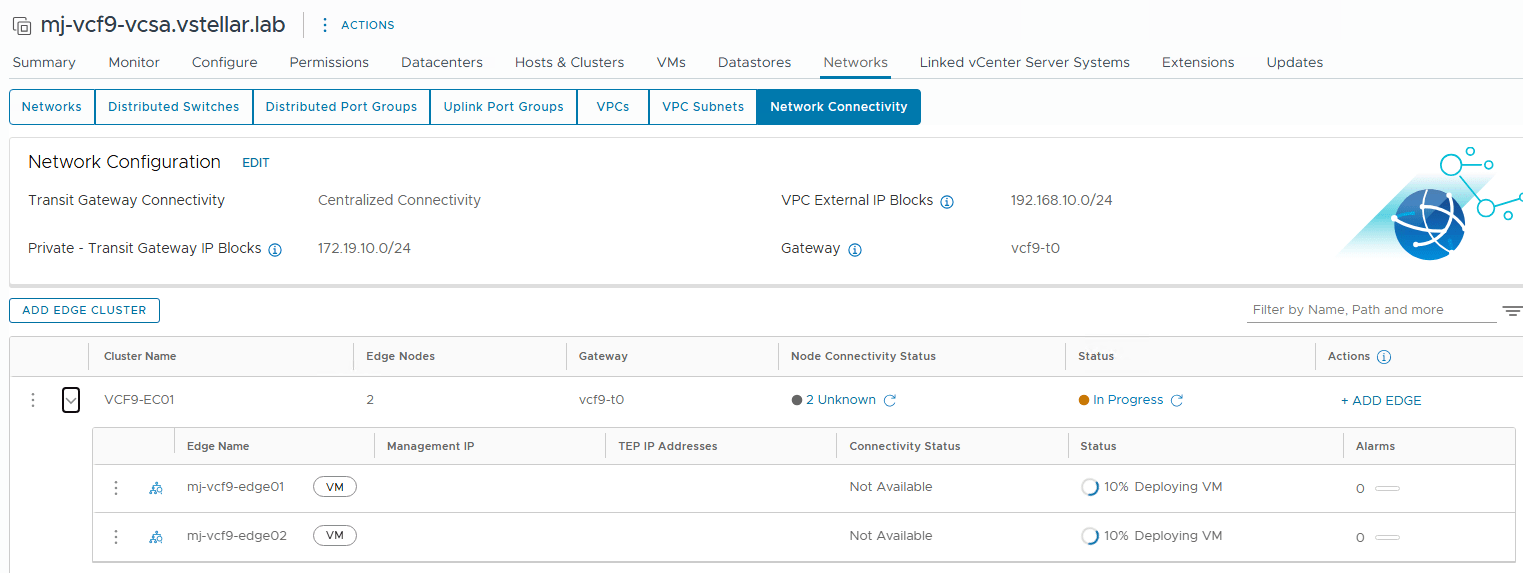
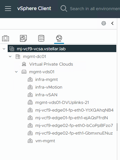
As discussed earlier, the installer wizard auto-creates the trunk port groups for the NSX Edges.
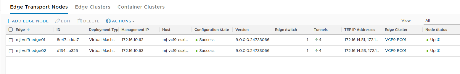
You can validate the Edge nodes deployment by logging in to the NSX Manager and navigating to the System > Fabric > Nodes tab and verifying node status and configuration state, etc.
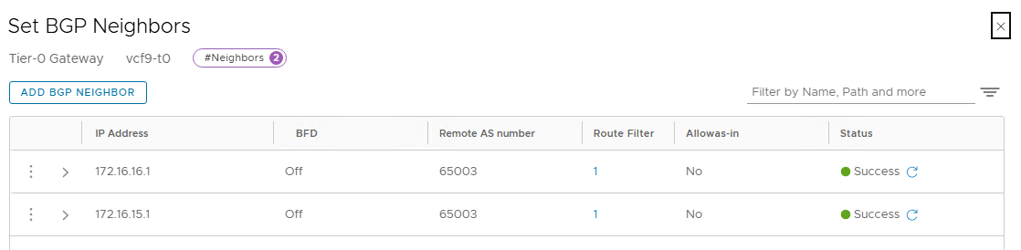
The tier-0 gateway is also created, and BGP neighbors are configured.
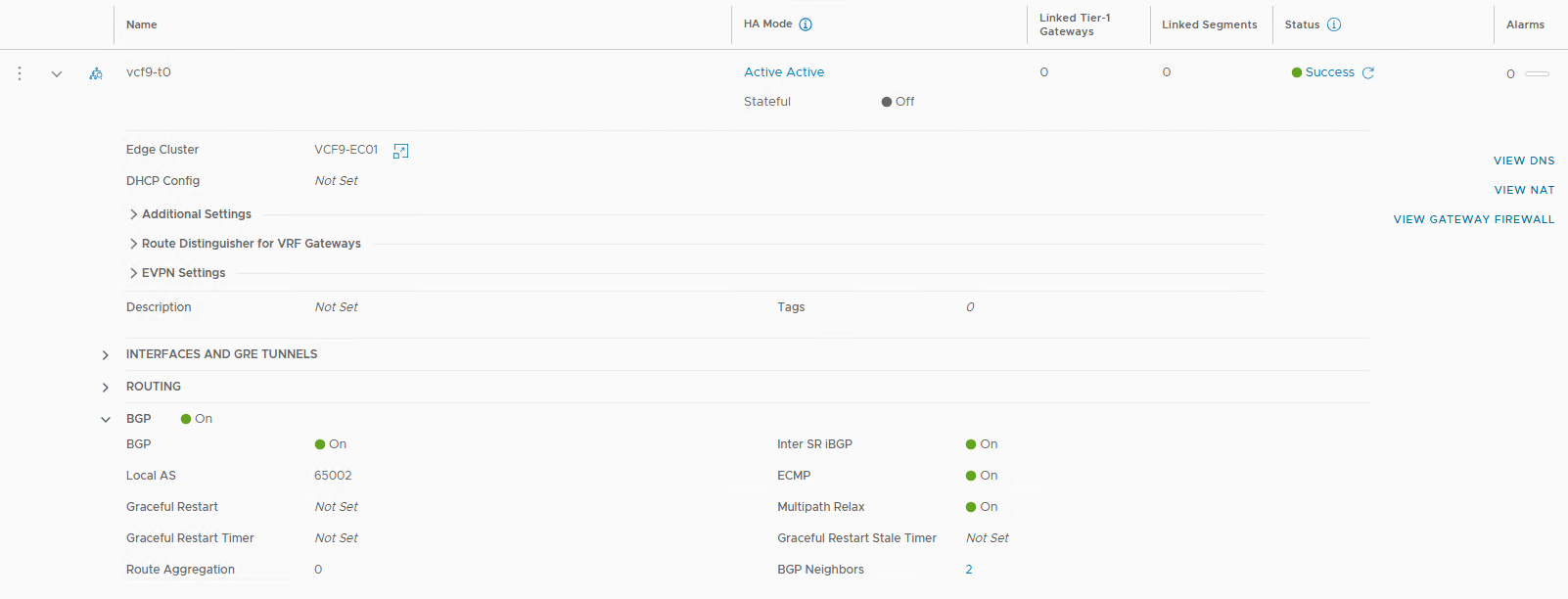
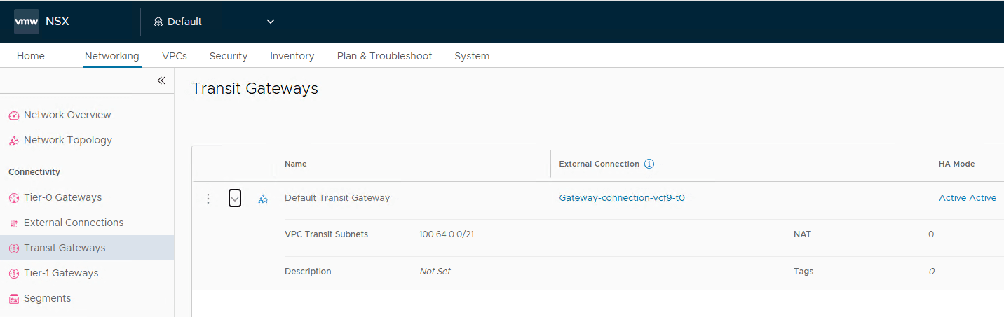
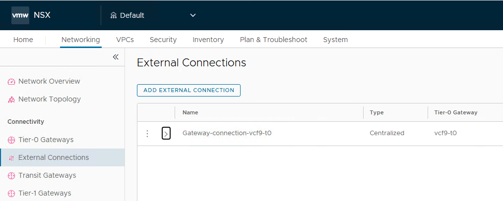
A transit gateway is auto-created and is connected to the tier-0 gateway.
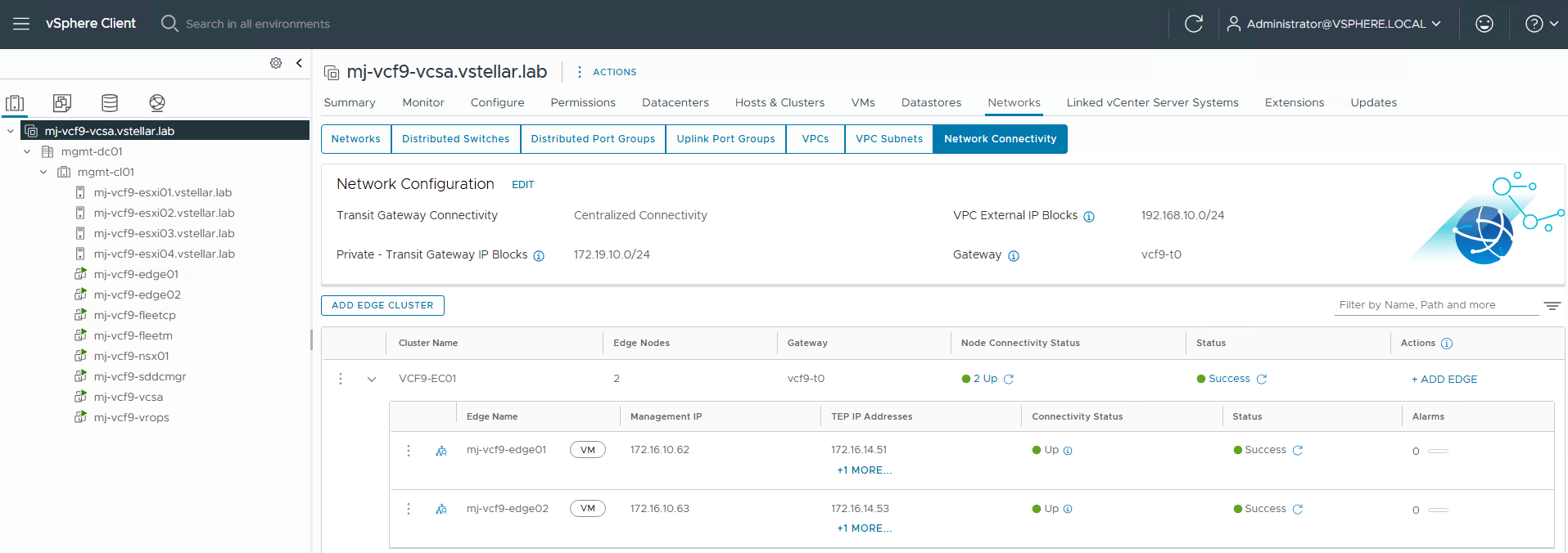
Edge node status as seen from vCenter UI.
And that’s it for this post. In the next post of this series, I will discuss the ESXi host commissioning process. Stay tuned!!!
I hope you enjoyed reading this post. Feel free to share this on social media if it is worth sharing.