
Welcome to part 3 of the VCF-9 series. Part 1 of this series dived into VCF-9 architecture and deployment models, and Part 2 showcased the deployment of a VCF instance using the new VCF installer. In this post, I will discuss the networking models available in VCF-9.
If you are not following along, I encourage you to read the earlier parts of this series from the links below:
1: VCF-9 Architecture & Deployment Models
In VCF 9, NSX introduces two networking object models: VPC Networking and Segment Networking.
VPC Networking: The VPC networking model offers a streamlined approach for configuring networking and security services, making it accessible even to non-networking experts. It aligns with the user experience found in public cloud platforms and integrates seamlessly within the VCF stack. Cloud users can interact with the VPC model through the NSX UI/API, vCenter UI, VCF Automation, or Supervisor cluster.
Segment Networking: The segment networking model is better suited for environments where the Network Admin maintains full centralized control over all network configurations, with no self-service options for users. While the VPC networking model also allows Network Admins to retain control, it is generally the recommended consumption model in VCF unless specific features exclusive to NSX segment networking are required.
VPC Networking Model
The VPC networking model consists of a 3-tier logical network and has the following components:
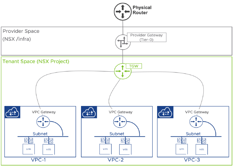
- Provider Gateway (Tier-0 Gateway): The provider gateway is a virtual router that connects the virtual network to the physical infrastructure. It handles dynamic or static routing to the physical network, advertising the network ranges of the virtual network, including public subnets, NAT IPs, and load balancer VIPs. In VCF 9.0, the provider gateway is essentially the same as the Tier-0 or VRF gateway found in the NSX segment networking model. The provider gateway can be shared among one or more tenants, enabling them to link their VPCs to the physical fabric via the transit gateway.
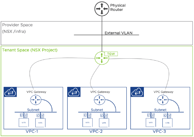
- Transit Gateway (TGW): The transit gateway’s primary role is to interconnect VPCs among each other and to the provider gateway. The transit gateway can bypass the provider gateway and directly connect to the physical fabric via an external VLAN, eliminating the need for NSX Edge nodes or any routing to the physical fabric. This setup is called the Distributed Transit Gateway (DTGW) because its functionality is fully distributed. DTGW does not support VCF Automation or Supervisor integration, as services like Source NAT and Load Balancing are unavailable. However, 1:1 NAT using an external IP can be configured for VPCs connected to a DTGW.
- VPC (Virtual Private Cloud): A VPC is a dedicated networking domain available to a cloud user, where workloads are connected based on network requirements. A VPC consists of subnets, which are essentially NSX logical networks in the VPC Networking Model. Each VPC is automatically assigned a VPC Gateway that routes traffic between subnets within the same VPC. East-West traffic is permitted unless restricted by a Distributed Firewall (DFW). Connectivity to external endpoints requires the VPC to be connected to a transit gateway (TGW) and depends on the type of subnet in which the workloads are placed. There are three subnet types within a VPC:
-
- Private VPC: Not routable outside the VPC. Workloads in a private VPC subnet require NAT to communicate with external workloads.
- Private TGW: Not routable north of the TGW. Workloads on a private TGW subnet need NAT to communicate with workloads north of the TGW but can connect with workloads south of it.
- Public: Routable north of the TGW. Workloads in a public subnet are generally accessible from external endpoints, depending on the routing configuration of the provider gateway.
The diagrams below, taken from the VCF 9.0 NSX design guide, illustrate the architecture of the VPC networking model.
VPC Networking Model with Centralized TGW
VPC Networking Model with Distributed TGW
The table below lists the major differences between the 2 gateway connectivity types:
| Feature | Centralized Connectivity | Distributed Connectivity |
| External IP (1:1 NAT) | No | Yes |
| NAT (SNAT/DNAT) | Yes | No |
| VPC Default Outbound NAT | Yes | No |
| DHCP (distributed) | Yes | Yes |
| E/W Firewall | Yes | Yes |
| N/S Firewall | Yes | No |
| AVI Load Balancer | Yes | Yes |
| VCF Automation | Yes | No |
| Supervisor Integration | Yes | No |
When setting up a centralized external connection for VPCs, the Transit Gateway SR component has the same span as the connected Tier-0 gateway SR. In other words, Transit Gateway SR is distributed across the same NSX Edge VMs that host the Tier-0 Gateway. Each TGW Service Router (SR) is tightly coupled with its corresponding Tier-0 SR.
This deployment can operate in either active/active or active/standby mode. The differences in the service supportability are outlined in the table below:
| Feature | Centralized Active/Standby | Centralized Active/Active |
| External IP (1:1 NAT) | Yes | Yes |
| NAT (SNAT/DNAT) | Yes | Yes |
| VPC Default Outbound NAT | Yes | No |
| DHCP | Yes | Yes |
| E/W Firewall | Yes | Yes |
| N/S Firewall | Yes | No |
| AVI Load Balancer | Yes | Yes |
Segment Networking Model
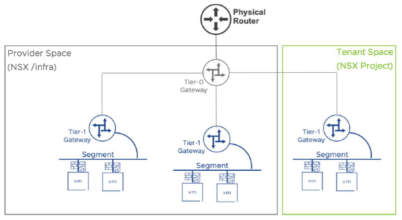
The Segment Networking model is a 2-tier logical network layout that has been known to NSX users for ages and is based on the following components:
- Tier-0 Gateway: The Tier-0 Gateway is essentially the same as the provider gateway in the VPC Networking model. It connects the physical infrastructure to the virtual network. It supports both dynamic and static routing, advertising the network ranges of the virtual network. The Tier-0 Gateway is always managed by the provider admin.
- Tier-1 Gateway: The Tier-1 Gateway serves as the default gateway for workloads connected via logical segments. A Tier-1 Gateway cannot connect directly to the physical fabric; it must connect to a Tier-0 Gateway. Tier-1 Gateways can be managed either by the Provider Admin or by a Tenant Admin (if created as part of an NSX Project). A typical NSX deployment has one or more manually configured Tier-0 Gateways, with a larger number of Tier-1 Gateways, depending on application needs. The Tier-1 Gateway is similar to the VPC Gateway in the VPC Networking Model.
- Segment: A segment represents an NSX logical network in the NSX segment model. Segments can be managed by either the provider admin or the tenant admin when created as part of an NSX Project. Typically, segments are connected to tier-1 gateways. The Segment object corresponds to the VPC Subnet object in the VPC Networking Model.
And that’s it for this post. This post is focused on providing a basic understanding of the networking constructs in VCF 9. I will dive into networking in great depth in the upcoming blog posts of this series.
I hope you enjoyed reading this post. Feel free to share this on social media if it is worth sharing.