In first post of this series, we learnt how to deploy NSX-T managers to form the management & control plane. In this post we will learn about uplink profiles and their use cases.
What is uplink Profile?
An uplink profile defines policies for the links from hypervisor hosts to NSX-T logical switches or from NSX Edge nodes to top-of-rack switches.
Uplink profiles allow you to consistently configure identical capabilities for network adapters across multiple hosts or nodes.
What settings we define on uplink profile?
The settings defined by uplink profiles include teaming policies, active/standby links, transport VLAN ID (ESXi TEP VLAN) and the MTU setting.
Before diving deep into uplink profiles, lets first discuss about various teaming policies that are available with uplink profiles.
There are 3 teaming policies that can be configured while creating an uplink profile:
- Failover Order: In this policy we specify one active uplink and one standby uplink. If this policy is configured in an uplink profile, then in case of active uplink (NIC) failure, all traffic is switched to the standby uplink.
- Load Balance Source: This policy can have multiple active uplinks so that load can be distributed across all the physical NIC’s. Each interface on the transport node is pinned to one active uplink
- Load Balance Source MAC: This is similar to Load Balance source teaming policy but instead of determining the uplink based on the source port, this policy determines the uplink based on the source VM’s MAC address. This policy is recommended when doing Guest VLAN trunking (where multiple MAC addresses are coming from the same port-ID)
Named Teaming Policy
Named Teaming Policy feature was first introduced in NSX-T 2.3 and it has the following common use cases:
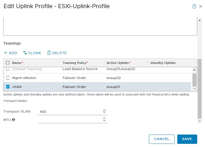
1: Traffic Pinning: There are various type of traffic that flows in an SDDC. These include management traffic, vSAN traffic, vMotion traffic etc. Using named teaming policy we can tie a particular type of traffic to a given uplink.
Named teaming policy is leveraged when you want all SDDC traffic to flow only through NVDS and not use vSphere VDS at all.
Note: We can use both default teaming policy & named teaming policy in same uplink profile. Named teaming policy can only be used with VLAN backed segments (logical switches)
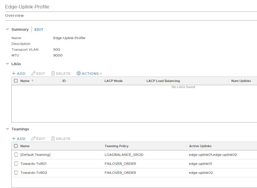
2: Providing deterministic NSX-T Edge Peering with a ToR switch via a single pNIC. As a best practice, BGP between edge nodes and ToR switch, should be configured with a dedicated VLAN and Uplink to make sure that in event of a component failure, traffic can be failed over to the other ToR switch.
Consideration for Edge Uplink Profile
When edge nodes are deployed in VM form factor, standby uplinks are not supported. The uplink profile which is created for vm based edge nodes, must specify only one active uplink and no standby uplink.
Edge VM supports multiple active uplinks for TEP configuration. In the uplink profile which we create for edge nodes, we can configure Load Balance Source Teaming Policy which allows to have two TEP’s on edge nodes and each TEP can be bound to a specific pNIC which gives better load balancing capabilities.
Create Uplink Profiles
Hope you have now some understanding of uplink profiles. Let’s dive into lab and start configuring these profiles.
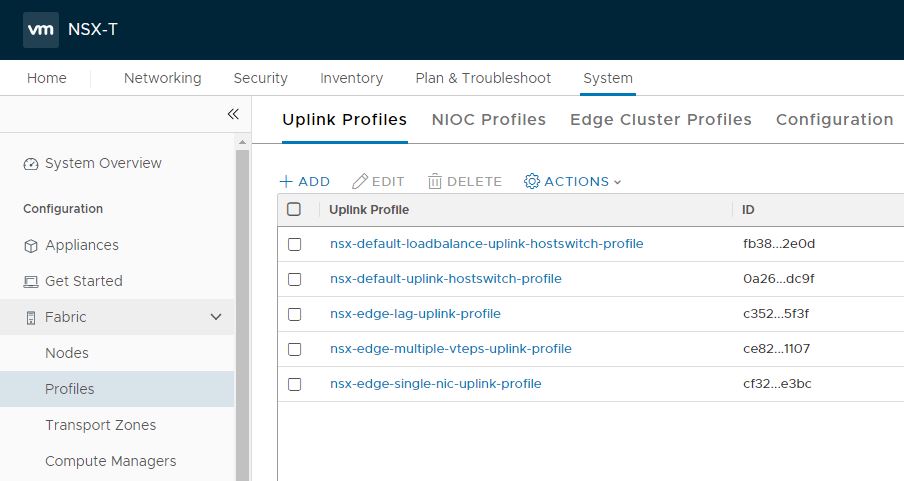
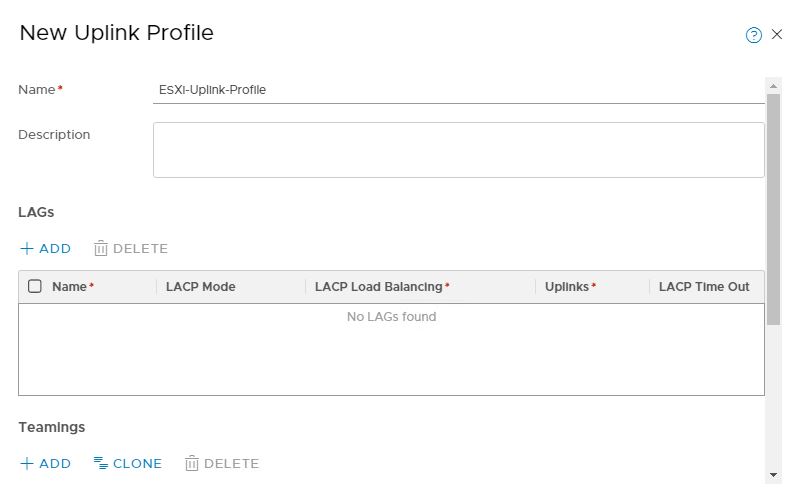
Login to NSX-T manager and navigate to Home > System > Fabric > Profiles and click on Add button to create a new uplink profile.
Provide a name for the profile and optional description.
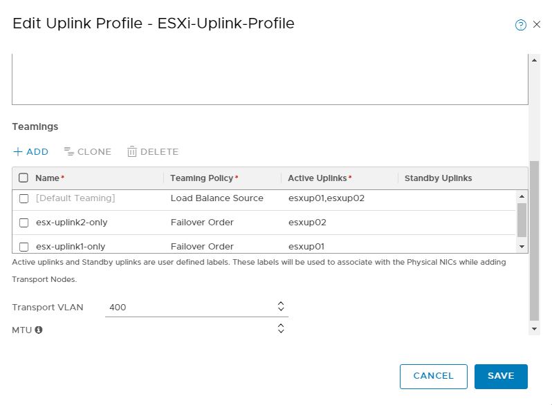
under Teamings, edit the default teaming policy and specify active uplinks. You can name your uplinks whatever you want. Uplink names here are just for your understanding.
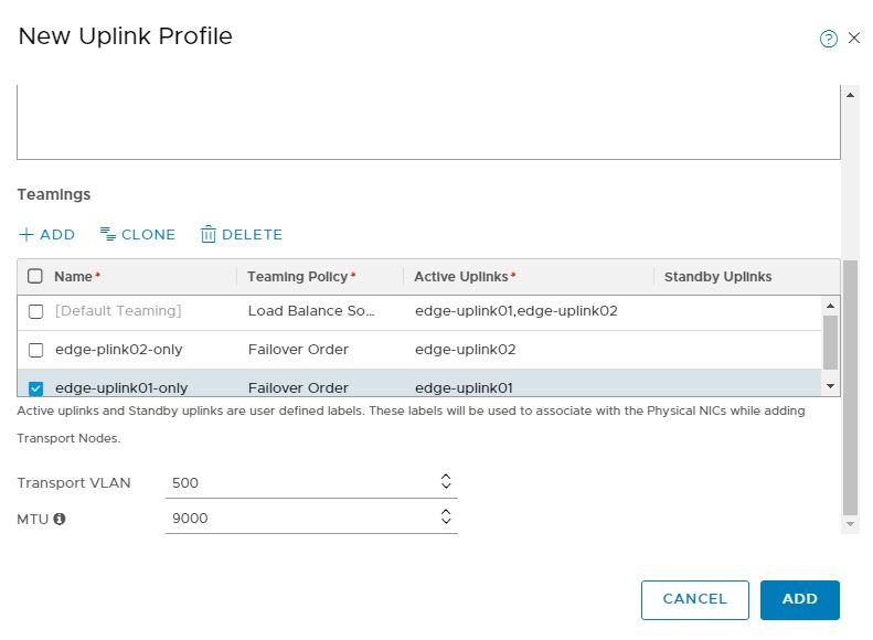
Also specify Edge TEP VLAN in transport VLAN. Default MTU value for uplink profile is 1600.
Note: If you are on planning to use NVDS along with VDS in your environment, you can create your own named teaming policies s well. For a CVDS (converged VDS) implementation, named teaming policy is not needed.
Similarly create a profile for Edge node uplinks.
And that’s it for this post.
In next post of this series, we will learn about setting up transport zones and transport node profiles.
I hope you enjoyed reading this post. Feel free to share this on social media if it is worth sharing 🙂

Great info::
Let’s say we have converged VDS, with VLAN backed segment V10, VTEP is on transport vlan 20. Converged VDS has two uplinks up1 and up2. Can we do following?
TEP traffic pinned to uplink1,
V10 traffic pinned to uplink2.
I could not find any info how to do this on on converged VDS.
Thanks !!