
In the last post of this series, we configured transport zones and transport nodes. We discussed the modes of transport zone and N-VDS.
In this post, we will learn how to create logical switches in NSX-T, and we will test connectivity between VMs attached to the same logical switch.
If you are not following along with this series, then I recommend reading earlier posts of this series from the links below:
4: NSX Controllers Automated Deployment
5: NSX Controllers Manual Deployment
6: Prepare Esxi host to form NSX-T Fabric
8: Configuring Transport Zone and Transport Nodes
A logical switch provides layer 2 connectivity for the virtual machines that are attached to it. In the last post, we discussed that transport zones are of two types (overlay and VLAN), and the type of logical switch is based on which type of transport zone it connects to.
When logical switches are attached to transport zones, they connect to the N-VDS for networking. A logical switch, when deployed, creates a broadcast domain to allow isolation of the VMs running in the infrastructure.
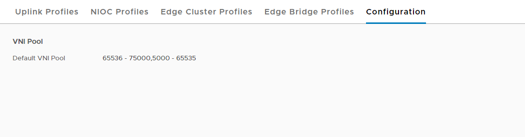
When logical switches are created, they are assigned a VNI from the pool defined by the administrator. These VNIs are very much similar to VLAN IDs but have a much higher range than VLAN (4094).
Information about the VNI pool can be viewed by logging into NSX Manager and navigating to Home > Fabric > Profiles > Configuration. You can edit the default pool and create a custom range as per your infrastructure requirements.
Let’s walk through the process of creating logical switches.
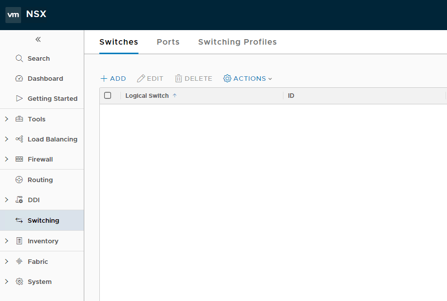
To create a new logical switch, navigate to Home > Switching > Switches and click on the + Add button.
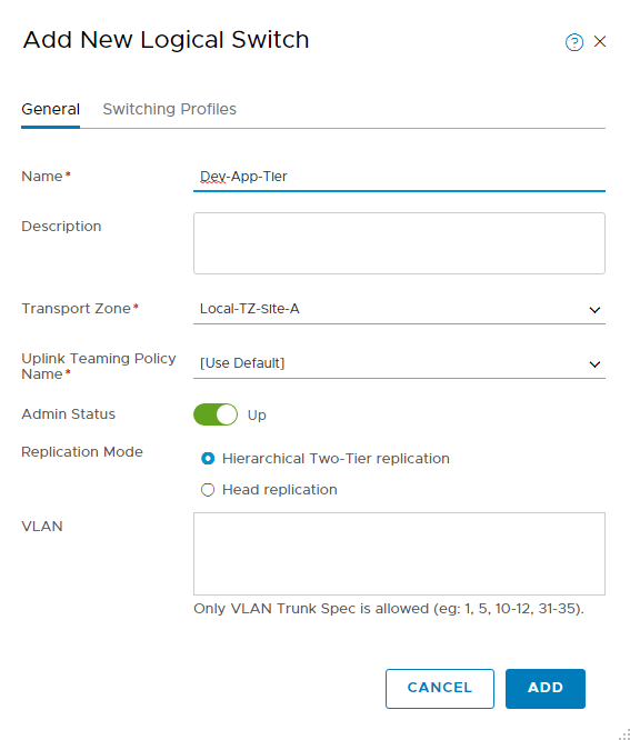
- Provide a name for the switch and select the transport zone to which this logical switch can connect.
- Uplink teaming policy can be left to default for lab configuration, and admin status should be set to up.
- Select the appropriate replication mode and enter the VLAN ID (only if the transport zone is VLAN-based and not overlay).
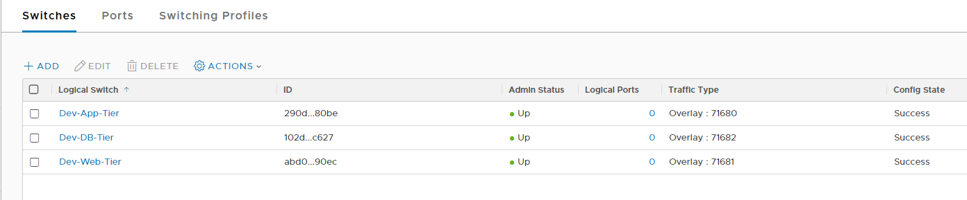
Make sure the admin status for your logical switches reads as “up” post creation and the config state as “success.”
At the vCenter level, you will see these logical switches appearing as port groups but with a slightly different icon than regular port groups. These port groups are known as an opaque network in NSX-T terms.
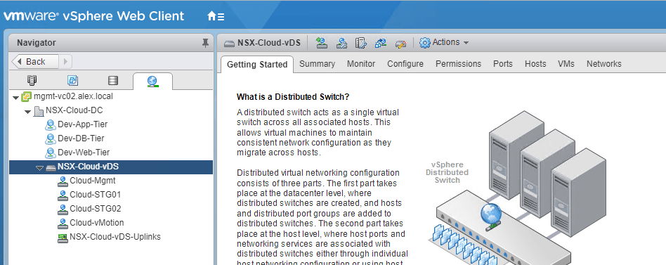
Unlike NSX-v, I did not find any option to attach VMs to the newly created logical switches. So to add VMs to these, you need to edit the VM settings and change the NIC connection to these port groups, which belong to logical switches.
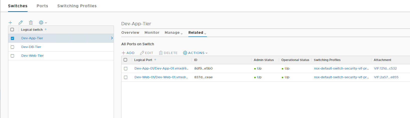
To list the VMs that are connected to a logical switch, you can click the logical switch and go to the Related tab.
I added my app and web VM to my Dev-App-Tier logical switch.
I am going to test the communication between the 2 VMs.
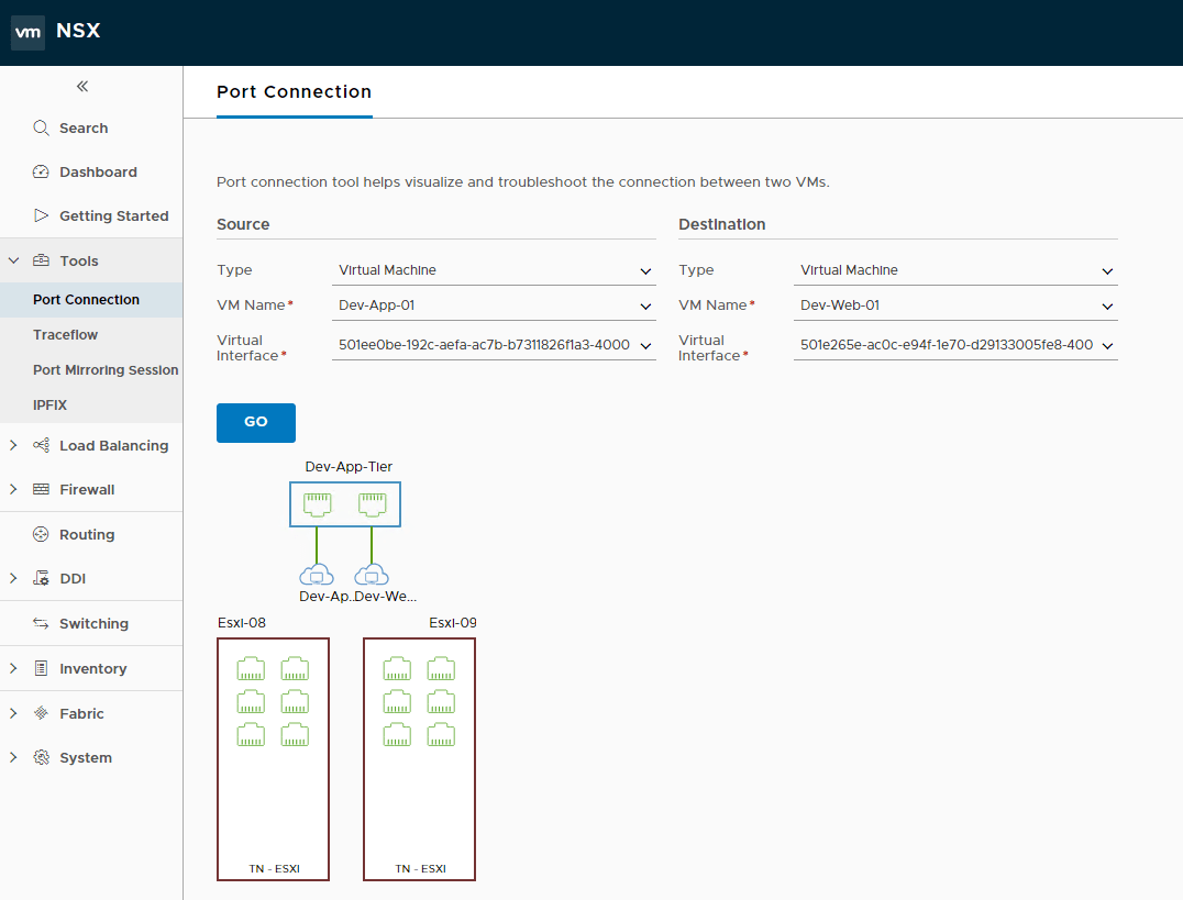
Also, if you navigate to the Port Connection tab, it will show you the relationship between the 2 VMs, i.e., if they are connected to the same or different logical switches and whether or not they are running on the same host.
Testing Logical Switch Connectivity
Now it’s time to test whether or not the 2 VMs that I added to the Dev-App-Tier logical switch are able to communicate with each other.
I put my App and Web VMs on the 10.10.10.0/24 network, with the App VM having IP 10.10.10.2 and the Web VM having 10.10.10.3.
I initiated a ping from the app to my web VM and got a ping reply. Also, the ARP table was populated with the entry of the VM that I just pinged.
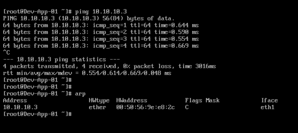
Then I pinged from the web to the app VM and got a response, and the ARP table now had an entry of the IP and Mac address of the App-01 VM.
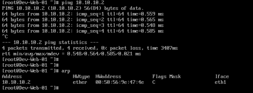
So the connectivity between the 2 VMs is established.
And that’s it for this post. In the next post of this series, we will learn about logical routing
I hope you enjoyed reading this post. Feel free to share this on social media if it is worth sharing.