In last post of this series we discussed about Logical Switching and understood when do we use logical switching. Also we deployed our first logical switch and moved a VM over to the newly created switch.
In this post we will discuss about Distributed Logical Router and look at the terms and terminology associated with it. We will not be diving into lab in this post as I intend to this in next post of this series
If you have missed earlier posts of this series, you can read them from below links:
2: Installing and Configuring NSX Manager
4: Preparing Esxi Hosts and Cluster
5: Configure VXLAN on the ESXi Hosts
Overview
Physical Routers are the building block of any network infrastructure. They are essential for building a working network topology. As we know Routers comes into picture when we need communication between 2 different subnets. The problem with physical networking was that the topology becomes more and more complex as infrastructure is scaled out and the network devices had to process a lot of East-West and North-South traffic.
SDN has simplified the networking and helped in breaking the silos of traditional physical networking. As we need routers in physical environments, we need to have similar capabilities in virtual networking world also.
With VMware NSX-v Routing between IP subnets can be performed in a logical space without traffic going out to the physical router. This routing is performed in the hypervisor kernel with a minimal CPU and memory overhead. This functionality provides an optimal data-path for routing traffic within the virtual infrastructure.
What is a DLR?
The Distributed Logical Router, or DLR, does what it says, it routes: it’s a router.
Like traditional routers, we can configure and use routing protocols such OSPF, IS-IS & BGP. DLR also provides a very cool feature known as “Layer 2 bridging”, which allows NSX VXLAN Logical Switch port group to talk to the regular VLAN out there on physical switch.
Distributed routing provides an optimized and scalable way of handling East – West traffic within a data center. If you are not familiar with what is East – West traffic, then it is the traffic which originates when virtual machines within a datacenter talk to each other. As virtualization has grown over time, virtual machines had replaced the physical servers and thus the amount of East–West traffic in the datacenter is growing.
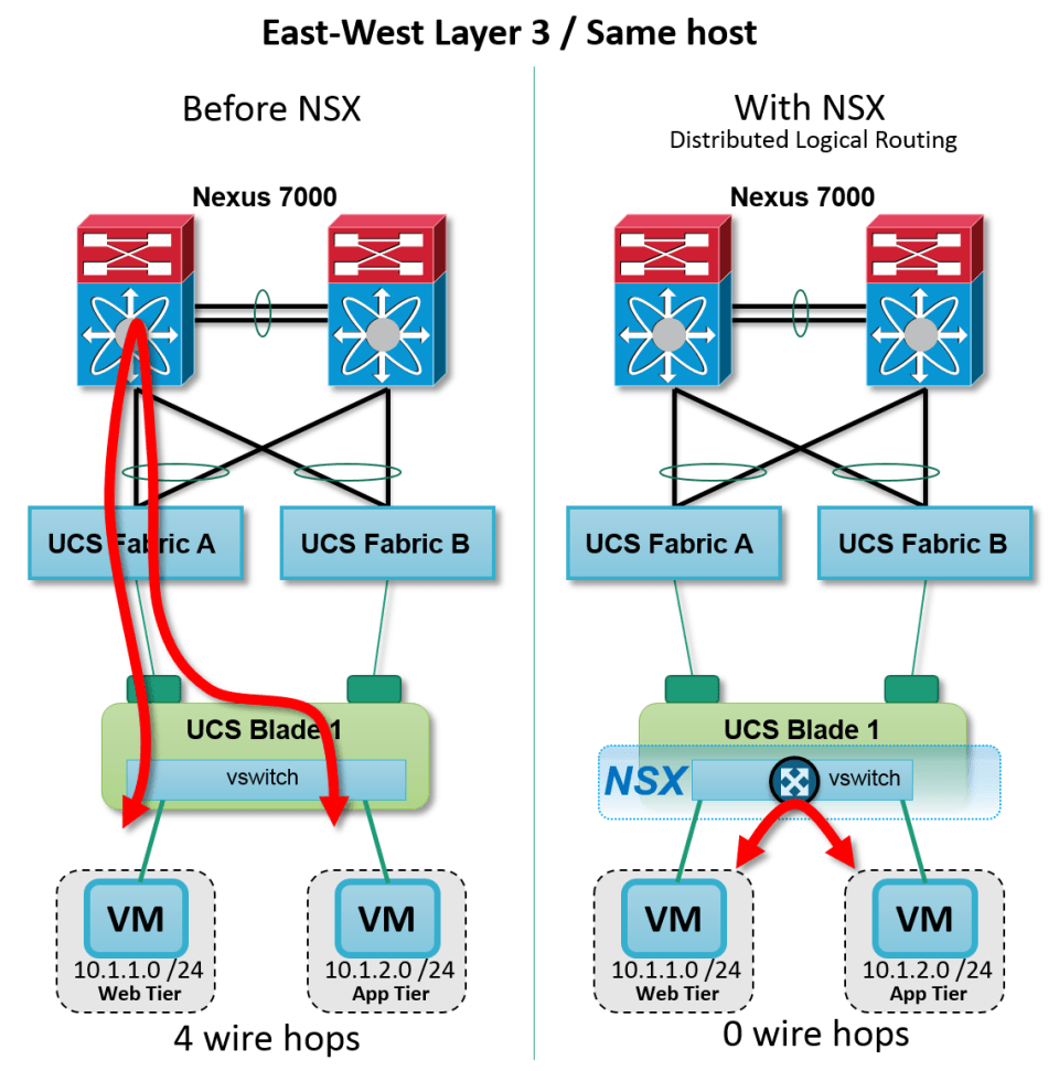
In a vSphere environment virtual machines that are connected to different subnets (portgroups) want to communicate with each other, the communication between these VM’s has to go via physical adapter connected to the Esxi host to the physical switch and then it traverse to physical router which in turn does the routing and routes packets accordingly. The packets then follow the reverse path and reaches to destination VM. This non optimal flow of packet is referred to as “hair-pinning”
Distributed Router in VMware NSX prevents “hair pinning” by providing hypervisor level routing. Each hypervisor has a routing kernel module that performs routing between the logical interfaces (LIFs). We will discuss about LIF’s shortly.
Components of DLR
A DLR consists of following components:
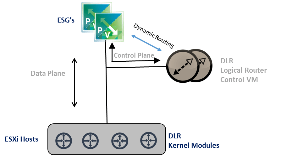
- Data plane : Data plane is kernel module installed on each vSphere host. DLR get installed on vSphere hosts along with VXLAN and DFW modules when we prep it ( we have done this activity in previous post of this series.
- Control Plane : Control plane is made up of virtual machines running as what we call as Logical Router Controller or LRC. Every time Distributed Router is deployed, a “Control VM” is deployed alongside.
- LRC VM’s are the supervisor Module. They are responsible for doing the routing updates, pairing or neighbor relationship with Edge service gateways or other physical routers and then it passes that information to NSX controllers and down to the vSphere hosts. Controller VM’s are not in data plane and data continues to flow even if controller vm’s are down, but you will not get routing updates or changes. When no control VM is available, packets are routed with last known configuration.
- Management Plane : The management plane for Distributed Logical Routers is, like every other NSX component, part of the vSphere Web Client. You’ll find everything you need to configure and manage your Distributed Router Instances under the NSX Edges tab.
Logical Interfaces (LIF’s)
The distributed logical router possess and manage the logical interfaces (LIF’s). The LIF concept is similar to VLAN interfaces on a physical router. A DLR can have a maximum of 1,000 LIF’s. We discussed above that the routing kernel module present on each vSphere host performs routing between the LIFs.
When the LIF is connected to a VLAN, the LIF has a pMAC and when the LIF is connected to a VXLAN, the LIF has a vMAC.

Where does DLR fit in to NSX infrastructure?
The recommended use case for Distributed Logical Routers is East-West traffic. We already discussed above what is a East-West traffic. DLR helps in reducing East-West traffic as each vSphere host is capable of doing L3 routing and thus virtual machine communication traffic do not need to go out to physical router to get routed.
For handling North-South traffic (traffic that leaves your virtual infrastructure or datacenter),VMware recommendation is to use Edge Service Gateways. The main benefit of using Distributed Routers is to take advantage of the optimized data path that network takes when routed by a DLR. Using DLR’s you can avoid “hairpinning” problems and thus can achieve a low packet transit time and saves network bandwidth.
Below diagram taken from a cisco UCS environments explains how NSX reduces East-west or North-South traffic.

For a deep-dive on different use cases for DLR or other NSX architecture related knowledge, have a look on this awesome document from VMware: Architecting-a-VMware-NSX-Solution
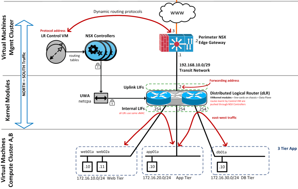
The below diagram gives a high level overview of how DLR fits into your infrastructure.

DLR Interfaces type
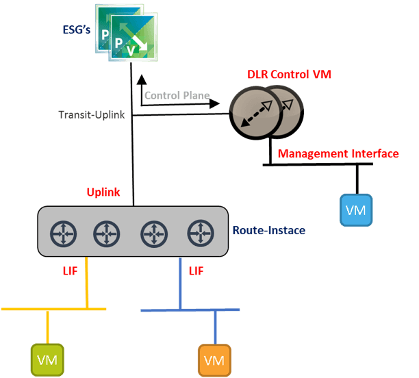
In DLR we have three types of interfaces. These are called Uplink, LIFs and Management.
Uplink: This connects the DLR Control VM to the upstream router. In some documents you will see that uplink is also referred to as “transit”, and this interface is the transit interface between the logical space to the physical space. The DLR supports both OSPF and BGP on its Uplink Interface, but cannot run both at the same time. We can only enable OSPF on a single Uplink Interface.
LIFs: LIFs exist on the ESXi host at the kernel level; LIFs are the Layer 3 interface that act as the default gateway for all VM’s connected to logical switches.
Management: DLR management interface can be used for different purposes. The first one is to manage the DLR control VM remote access like SSH. Another use case is for High Availability. The last one is to send out syslog information to a syslog server.
The management interface is part of the routing table of the control VM; there is no separate routing table. When we configure an IP address for the management interface only devices on the same subnet as the Management subnet will be able to reach the DLR Control VM management IP, and the remote device will not be able to contact this IP.
The below image is diagrammatic explanation of above.

DLR Interfaces Type
I will wrap my post here else it will be a super large boring post, but believe me world of DLR has not finished yet. A lot of things about DLR is yet to cover, but instead of writing up everything here, I would recommend reading below articles from fine gentlemens.
1: How Distributed Routing or DLR works by Joseph Griffiths
2: A deep dive into NSX Distributed Routing by Roie Ben Haim
3: Distributed virtual and physical routing in VMware NSX for vSphere by Brad Hedlund
In next post of this series we will deploy a DLR and see how to configure it. Stay Tuned!!!
I hope you enjoyed reading this post. Feel free to share this on social media if it is worth sharing. Be sociable

6 thoughts on “Learning NSX-Part-7-Distributed Logical Router Tidbits”