F5 to Avi Load Balancer Migration – Part 5: Offline Mode Migration

Welcome to part 5 of the F5 to Avi migration series. The previous posts in this series discussed the online mode migration of the load balancer from F5 to Avi. In this post, I will demonstrate the offline mode migration.

If you are not following along, I encourage you to read the earlier parts of this series from the links below:

1: Introduction to F5 to Avi Load Balancer Migration

2: F5 to Avi – Migration Strategy Framework

3: Avi Assessment Framework

4: F5 to Avi Online Mode Migration

Offline migration is typically needed when you want to migrate F5 BIG-IP configurations to AVI without direct connectivity between systems or in air-gapped environments. To convert the F5 objects, you manually upload the F5 configuration file (bigip.conf), certificates, and keys to the conversion tool.

To perform offline migration, login to the conversion tool and navigate to the Migrate tab, and click Start.Read More

F5 to Avi Load Balancer Migration – Part 4: Online Mode Migration

Welcome to part 4 of the F5 to Avi migration series. The previous posts in this series aimed to provide a comprehensive framework for the F5 to Avi migration strategy and planning migration waves. In this post, I will demonstrate how to migrate load balancer objects between the 2 platforms.

If you are not following along, I encourage you to read the earlier parts of this series from the links below:

1: Introduction to F5 to Avi Load Balancer Migration

2: F5 to Avi – Migration Strategy Framework

3: Avi Assessment Framework

Avi Load Balancer Conversion Tool

To migrate load balancer objects from F5 to Avi, VMware provides a migration tool called “Avi Load Balancer Conversion Tool (ALBCT),” a UI-based conversion tool that automates and simplifies migration of existing F5 load balancer configurations to the Avi Load Balancer platform.The conversion tool helps you:

  1. Import configuration files from existing load balancers (F5).
Read More

F5 to Avi Load Balancer Migration – Part 3: Identifying Migration Candidates

Welcome to part 3 of the F5 to Avi migration series. Part 1 of this series discussed use cases of Avi migration, and part 2 dived into the migration framework that you should follow for a successful error-free migration.

If you are not following along, I encourage you to read the earlier parts of this series from the links below:

1: Introduction to F5 to Avi Load Balancer Migration

2: F5 to Avi – Migration Strategy Framework

Overview

Not all F5 virtual services and configurations are equally suited for immediate migration to Avi. A strategic assessment helps prioritize migrations, manage risks, and allocate resources effectively. In this post I will try to provide a comprehensive framework for evaluating F5 objects and determining migration candidacy.

Step 1: Understand the Goal of Migration

Before identifying good candidates, clarify the purpose:

  • Are you moving to reduce licensing costs (F5 → NSX ALB built into NSX or vSphere+ licensing)?
Read More

F5 to Avi Load Balancer Migration – Part 2: Migration Strategy Framework

In the first post of this series, I discussed the top reasons why an organization wants to move from F5 to Avi load balancer. In this post, I will discuss the migration strategy for a successful migration.

To migrate from F5 to Avi Load Balancer, VMware provides a free Avi Load Balancer Conversion Tool (ALBCT) that automates the translation of F5 BIG-IP configurations. The migration process involves using this tool to convert the F5 load balancer configuration and then cutting over traffic to the Avi-based environment.

Migration Strategy: An Eight-Stage Approach

The key to successful migration is meticulous planning, comprehensive testing, and leveraging Avi’s conversion tool to automate complex configuration transformations. With proper execution, organizations emerge with a modern, scalable, and easier-to-manage load balancing platform that supports their digital transformation initiatives.

The image below lists the various stages involved in the strategic planning for a successful migration.

Stage 1: Planning and Assessment

Before any technical work begins, thorough planning is essential.Read More

F5 to Avi Load Balancer Migration – Part 1: Introduction

Introduction

In today’s digital-first world, enterprises are under constant pressure to modernize infrastructure, adopt hybrid and multi-cloud architectures, and deliver applications faster.As enterprises accelerate their digital transformation journey, legacy load-balancing infrastructure is becoming a bottleneck. The rise of cloud-native applications, containerization, and the need for operational simplicity have prompted many organizations to evaluate modern alternatives.

F5 BIG-IP, while robust, lacks the agility, automation capabilities, and cloud-native architecture that modern applications demand. On the other hand, Avi Load Balancer, a software-defined, cloud-native alternative, offers organizations the flexibility to evolve their infrastructure with minimal disruption.

In this blog, I will cover the key use cases driving migration from F5 to Avi Load Balancer.

Use Cases for F5 to Avi Migration

Migrating from F5 to Avi helps organizations modernize their application delivery infrastructure, reduce operational complexity, and achieve cloud agility. Below are some common use cases for F5 to Avi migration.

1. Cloud and Multi-Cloud Strategy Enablement

Organizations are adopting multi-cloud architectures to avoid vendor lock-in and leverage best-of-breed services across providers.Read More

NSX 4.x VRF Gateways – Part 5: Inter-VRF BGP Route Leaking

Welcome to part 5 of the NSX VRF series. In part 4, I discussed Inter-VRF routing that enables communication between VRF gateways in NSX by exchanging the routes that are not BGP, e.g., connected, NAT, and static routes, etc. In this post, I will discuss how route exchange can be facilitated over BGP.

If you are not following along, I encourage you to read the earlier parts of this series from the links below:

1: NSX VRF Gateway – Architecture & Configuration

2: VRF Config Validation & Traffic Flows

3: VRF Route Leaking

4: Inter-VRF Routing

Introduction

Inter-VRF BGP route leaking allows routes learned in one VRF to be advertised to another VRF over BGP to enable communication between the isolated VRFs. It’s achieved through configuring BGP on Tier-0 VRF gateways and utilizing route maps and community lists to control the route leaking process.

BGP route leaking supports leaking both IPv4 & IPv6 address families.Read More

NSX 4.X VRF Issue “Overlapping Trunk VLAN on Logical Switch”

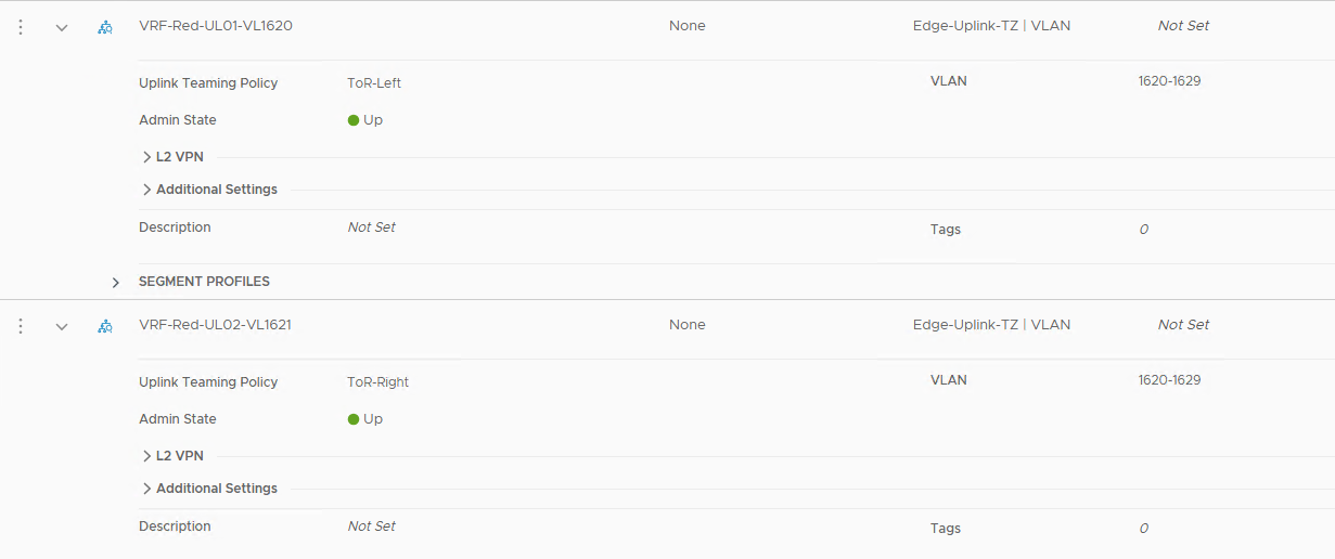
I came across an interesting issue while configuring VRF gateways in NSX 4.x. The configuration was erroring out with the message “Logical Switch trunk-vlan overlapping with another Logical Switch in the same underlying Edge host-switch is not allowed. Change VLAN configuration.”

After configuring the Tier-0 VRF Gateways, the parent Tier-0 went down.

Also, 2 out of 4 interfaces on the VRF gateway were stuck in the configuring state.

The Cause

The main cause of this issue was that I created 2 trunked segments for northbound connectivity and allowed the same range of VLANs on them.

This method used to work perfectly fine in NSX 3.x. I have blogged on this topic earlier. So, I was wondering why the same steps are not working.

While troubleshooting, I came across this post by Graham Smith on Broadcom’s community channel. He has provided the resolution in his blog post here.

In NSX 3.x,Read More

NSX 4.x VRF Gateways – Part 4: Inter-VRF Routing

Welcome to part 4 of the NSX VRF series. In part 3, I discussed VRF route leaking that allows communication between 2 data plane isolated VRF gateways in NSX.

In this post, I will discuss Inter-VRF routing.

If you are not following along, I encourage you to read the earlier parts of this series from the links below:

1: NSX VRF Gateway – Architecture & Configuration

2: VRF Config Validation & Traffic Flows

3: VRF Route Leaking

Inter-VRF routing was first introduced in NSX 4.1.0, and it allows exchanging routes between VRFs. The route exchange happens between VRFs over an internally plumbed Inter-VRF transit link.

You can configure Inter-VRF routing between:

  • Parent Tier-0 gateway and Tier-0 VRF gateway.
  • From Tier-0 VRF gateway to parent Tier-0 gateway.
  • From one Tier-0 VRF gateway to another Tier-0 VRF gateway.

To exchange routes between the gateways, you can use one of the following methods:

  • Inter-VRF Route Advertisement – Advertise routes that are not BGP, such as static, connected, NAT, etc, that are available as inter-vrf static routes on the connected gateway.
Read More

NSX 4.x VRF Gateways – Part 3: VRF Route Leaking

Welcome to part-2 of the NSX VRF series. Part 1 of this series discussed VRF architecture, and part 2 demonstrated data plane isolation between the VRF instances.

In this post, I will demonstrate how to establish communication between 2 VRFs using VRF Route Leaking.

If you are not following along, I encourage you to read the earlier parts of this series from the links below:

1: NSX VRF Gateway – Architecture & Configuration

2: VRF Config Validation & Traffic Flows

By default, the data plane traffic between VRF instances is isolated in NSX. You can exchange traffic between 2 VRFs by configuring VRF Route Leaking. In this technique, static routes are configured on the VRF gateways to steer traffic towards other VRF gateways.

There are 2 supported topologies for VRF route leaking:

  • Local VRF-to-VRF route leaking
  • Northbound VRF leaking

Note: A multi-tier routing architecture is required for traffic to be exchanged in a VRF leaking topology, as static routes pointing to Tier-1 distributed router (DR) uplinks are necessary.Read More

NSX 4.x VRF Gateways – Part 2: VRF Config Validation & Traffic Flows

Welcome to part-2 of the NSX VRF series. Part 1 of this series discussed VRF architecture and its use cases and the advantages that VRF offers over traditional routing isolation techniques. In this post, I will demonstrate VRF configuration validation to ensure things are working as expected.

The following configuration was done in vSphere before VRF validation:

  • VRF-Red VM is deployed and connected to segment “red-ls01” and has IP 192.168.40.2
  • VRF-Blue VM is deployed and connected to segment “blue-ls01” and has IP 192.168.50.2

Connectivity Test

The blue VRF VM can:

  • Ping its default gateway.
  • Uplink interface used for BGP peering.
  • An IP from the physical network.

However, the Blue VRF VM can’t ping the Red VRF gateway or any of its VMs.

The same tests were performed on the Red VFR VM and validated that it can’t reach the Blue VRF gateway or its VM.

You can run similar tests using the NSX Traceflow tool.Read More