
Welcome to part-2 of the NSX VRF series. Part 1 of this series discussed VRF architecture and its use cases and the advantages that VRF offers over traditional routing isolation techniques. In this post, I will demonstrate VRF configuration validation to ensure things are working as expected.
The following configuration was done in vSphere before VRF validation:
- VRF-Red VM is deployed and connected to segment “red-ls01” and has IP 192.168.40.2
- VRF-Blue VM is deployed and connected to segment “blue-ls01” and has IP 192.168.50.2


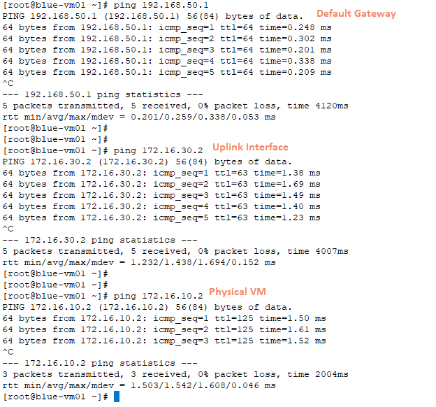
Connectivity Test
The blue VRF VM can:
- Ping its default gateway.
- Uplink interface used for BGP peering.
- An IP from the physical network.
However, the Blue VRF VM can’t ping the Red VRF gateway or any of its VMs.

The same tests were performed on the Red VFR VM and validated that it can’t reach the Blue VRF gateway or its VM.

You can run similar tests using the NSX Traceflow tool.

A red exclamation mark on the Tier-1 gateway means there is no route for the Blue VM (192.168.50.0/24 network)

The trace result shows all the hops that the packet took before it was dropped by the Tier-1 gateway.

Let’s review the routing table of the VRFs.
VRF Red BGP Neighbors

The Red VRF has no route for the Blue VRF network (192.168.50.0/24). It is learning a few routes from the northbound router because I have leaked the default VRF routing table into the Red VRF table at the physical layer.
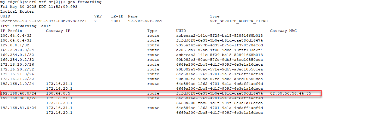
Also, the Red VRF has a direct route to the 192.168.40.0/24 via its tier-1 gateway.

The same is evident in the forwarding table of the VRF gateway.
Similar findings for the Blue VRF gateway. There are no BGP routes learned from the northbound router because the route leak between the default and blue VRF is not enabled on the router.


And that’s it for this post. In the next post, I will discuss how we can establish communication between VRFs using the route leaking technique.
I hope you enjoyed reading this post. Feel free to share this on social media if it is worth sharing.