In last post I covered the steps of configuring VRF gateways and attached Tier-1 gateway to VRF. In this post I am going to test my configuration to ensure things are working as expected.
Following configuration was done in vSphere prior to VRF validation:
- Tenant A VM is deployed and connected to segment ‘Tenant-A-App-LS’ and have IP 172.16.70.2
- Tenant B VM is deployed and connected to segment ‘Tenant-B-App-LS’ and have IP 172.16.80.2
Connectivity Test
To test connectivity, I first picked Tenant-A vm and performed following tests:
A: Pinged default gateway and got ping result.
B: Pinged default gateway of Tenant-B segment and got the result.
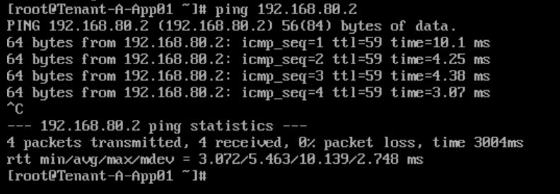
C: Pinged Tenant-B VM and got result.
D: Pinged a server on physical network and got ping response.
Same set of tests I performed for Tenant-B VM and all test results passed.
Traceflow
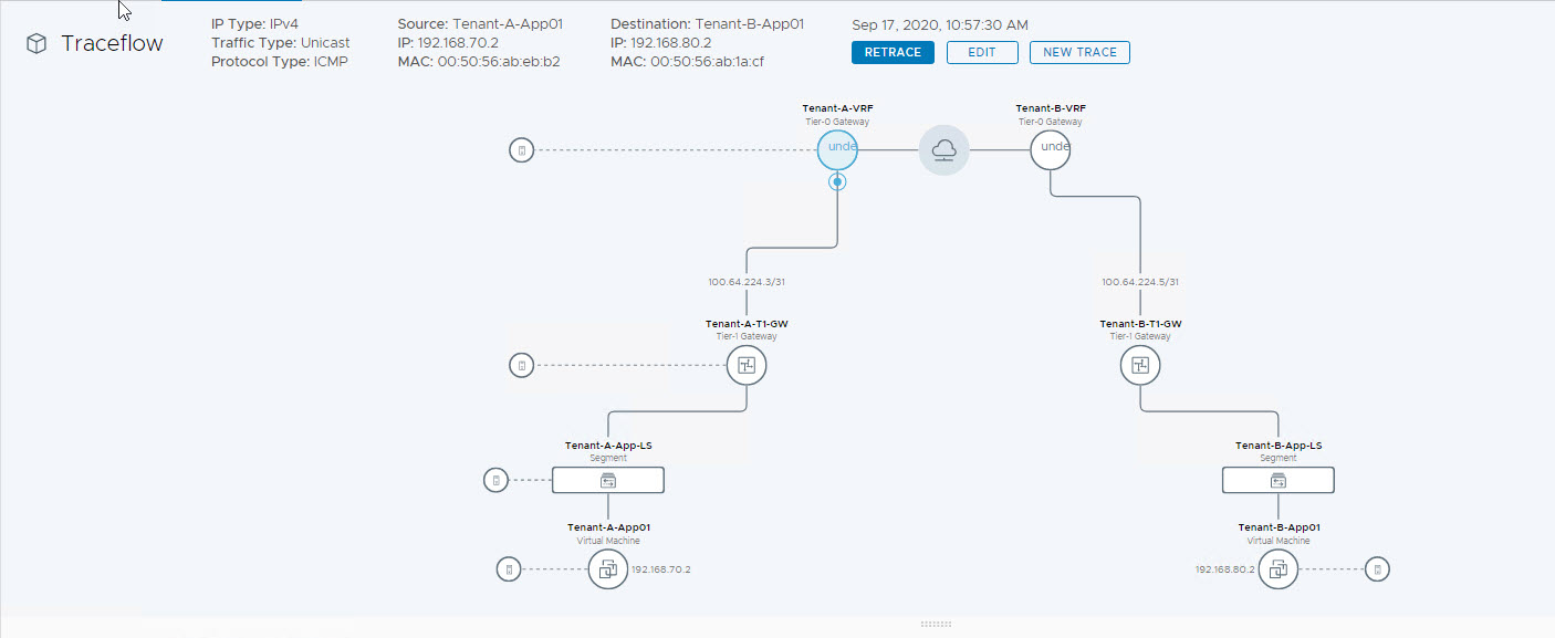
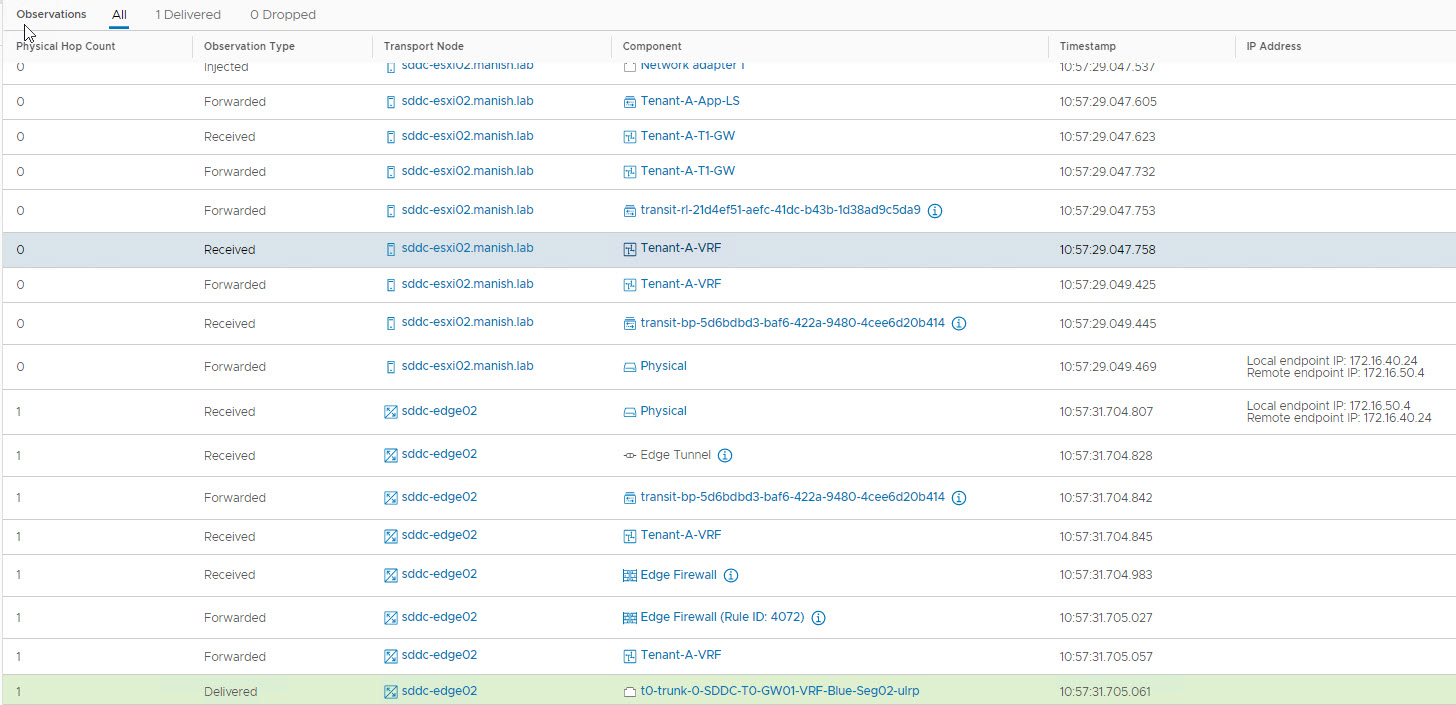
Traceflow is another way of testing connectivity between vm’s. Below are my traceflow results for the 2 vm’s:
Here is the topology diagram created by NSX-T to show path taken by packet from Tenant-A-App01 vm to Tenant-B-App01 vm.
And here is the actual packet flow.
Traceflow from Tenant-B-App01 > Tenant-A-App01
Lets connect to edge nodes and perform additional validations.
1: Let’s have a look into SR-DR components that gets created with VRF
|
1 2 3 4 5 6 7 8 9 10 11 12 13 |
sddc-edge01> get logical-router Logical Router UUID VRF Name Type Ports 736a80e3-23f6-5a2d-81d6-bbefb2786666 0 TUNNEL 4 e50c0f45-a6e4-46a9-a9fe-1d6c21bb5b49 1 SR-SDDC-T0-GW01 SERVICE_ROUTER_TIER0 10 3d6402de-a83b-400d-b4ba-b88522ec7964 3 DR-SDDC-T0-GW01 DISTRIBUTED_ROUTER_TIER0 4 de8199c0-d71d-474b-a67b-c45c3f11191b 4 SR-SDDC-T1-GW01 SERVICE_ROUTER_TIER1 5 ca9366ef-6b52-4809-8475-869d60450771 5 SR-VRF-Tenant-A-VRF VRF_SERVICE_ROUTER_TIER0 6 a32a8438-1a9c-435c-937c-b895cdab454b 6 SR-VRF-Tenant-B-VRF VRF_SERVICE_ROUTER_TIER0 6 21d4ef51-aefc-41dc-b43b-1d38ad9c5da9 7 DR-Tenant-A-T1-GW DISTRIBUTED_ROUTER_TIER1 5 5d6bdbd3-baf6-422a-9480-4cee6d20b414 8 DR-VRF-Tenant-A-VRF VRF_DISTRIBUTED_ROUTER_TIER0 4 7ff1bbfc-b5cb-433d-8c6c-50df19d320ee 9 DR-VRF-Tenant-B-VRF VRF_DISTRIBUTED_ROUTER_TIER0 4 5bccfca2-3e90-49db-865e-78500f9b84d0 10 DR-Tenant-B-T1-GW DISTRIBUTED_ROUTER_TIER1 5 |
From above table, we can see SR components for Tenant A & B VRF’s got created.
Since we have attached Tier-1 gateways to VRF, DR components also got created for the VRF’s.
Let’s connects to logical router SR-VRF-Tenant-A-VRF Logical and verify the BGP neighbor connectivity.
|
1 2 3 4 5 6 7 8 9 10 11 12 |
sddc-edge01> vrf 5 sddc-edge01(tier0_vrf_sr)> get bgp neighbor summary BGP summary information for VRF VRF-5121 for address-family: ipv4Unicast Router ID: 172.16.60.2 Local AS: 65003 Neighbor AS State Up/DownTime BFD InMsgs OutMsgs InPfx OutPfx 192.168.11.1 65001 Estab 21:52:47 NC 1321 1321 5 11 192.168.10.1 65001 Estab 21:52:47 DW 1321 1317 7 2 |
BGP Routing Table for Tenant-A
|
1 2 3 4 5 6 7 8 9 10 11 12 |
BGP Routing Table for Tenant-A sddc-edge01(tier0_vrf_sr)> get forwarding Logical Router UUID VRF LR-ID Name Type ca9366ef-6b52-4809-8475-869d60450771 5 5122 SR-VRF-Tenant-A-VRF VRF_SERVICE_ROUTER_TIER0 IPv4 Forwarding Table IP Prefix Gateway IP Type UUID Gateway MAC 0.0.0.0/0 192.168.10.1 route d7ccb673-5a8f-4423-b4d8-5b28ac1ed545 00:50:56:a7:2b:67 192.168.70.0/24 100.64.224.3 route a3e7ad68-231b-4e6b-b884-8c44bc2491b1 02:50:56:56:44:55 |
So things looks good from BGP prospective in my lab.
And that’s it for this post. In next post I will show how to configure Inter-VRF routing.
I hope you enjoyed reading this post. Feel free to share this on social media if it is worth sharing 🙂


