In last post of this series we briefly looked what is VXLAN (In actual it’s an ocean of knowledge in itself) and also we configured VXLAN on our cluster/hosts.
In this post we will be talking about Logical switching and we will see how to create that and will cover prerequisites part as well.
If you have missed earlier posts of this series, you can read them from below links:
2: Installing and Configuring NSX Manager
4: Preparing Esxi Hosts and Cluster
5: Configure VXLAN on the ESXi Hosts
Let’s start with introduction to Logical Switching.
What is Logical Switching?
Functionality of a Logical switch is very similar to that of a physical switch i.e they allow isolation of applications and tenants for security purpose. A logical switch when deployed, creates a broadcast domain to allow isolation of the VM’s running in infrastructure.
Logical switches provides you with capability of creating VLAN’s (similar to in physical world) and these VLAN’s not only provides isolation but can also span across large compute clusters.
The logical switch is mapped to a VXLAN that encapsulates the traffic going over physical network.
Logical switches can be created as either local or as universal (which can span across vCenter’s in a cross-vCenter NSX deployment architecture).
Why logical switching?
To answer this question I am not gonna include a long paragraph with complex networking terms. Instead I will ask a simple question that in a physical networking world why VLAN?
A cloud service provider or any organization can have multiple tenants running in their data center. In a public cloud environment a tenant can simply be referred as a customer while in an organization tenant can be the different departments of that organization.
Now these tenants are running their business critical applications deployed inside the VM’s running on top of virtualization stack and are sharing same piece of infrastructure (compute, storage and network).
Now the question arises how to stop each tenant from sneaking into other tenant’s VM or applications. These tenants require isolation from each other for various reason including security, fault isolation, and avoiding overlapping IP addressing issues.
So to solve the above problem we use logical switching.
Prerequisites for creating a Logical Switch
Before you go and start creating logical switches in your environment, you have to make sure you meet following requirements:
- vSphere distributed switches must be configured. You cannot deploy logical switches on standard switches.
- NSX controllers must be deployed.
- Your compute host clusters must be prepared and ready to go.
- VXLAN must be configured.
- A Transport Zone and a segment ID pool must be configured.
In our last post covered all the above requirements. So let’s jump into lab and start creating logical switches.
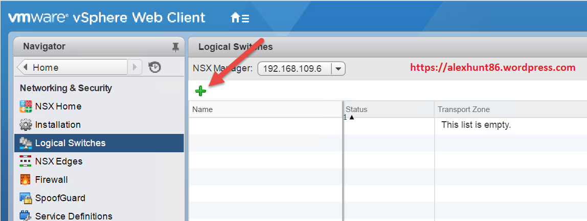
To start creating Logical Switch, Login to your vCenter server Web Client and navigate to Home | Networking & Security | Logical Switches
Click on the green “+” button to start creating a new Logical Switch
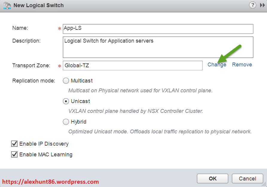
2. Provide a name and nice little description for your logical switch. Select the transport zone to which this logical switch will be mapped.
Also select the replication mode for the logical switch.
Note:
By default, the logical switch inherits the control plane replication mode set in the Transport Zone. You can change this by selecting one of the available modes.
IP discovery is enabled by default and allows Address Resolution Protocol (ARP) suppression between VMs connected to the same logical switch. There should not be any reason to disable this (optional).
Enable MAC learning setting if your virtual machines are having multiple MAC addresses or using virtual NICs that are trunking VLANs. This setting builds a VLAN/MAC pairing table on each vNIC.
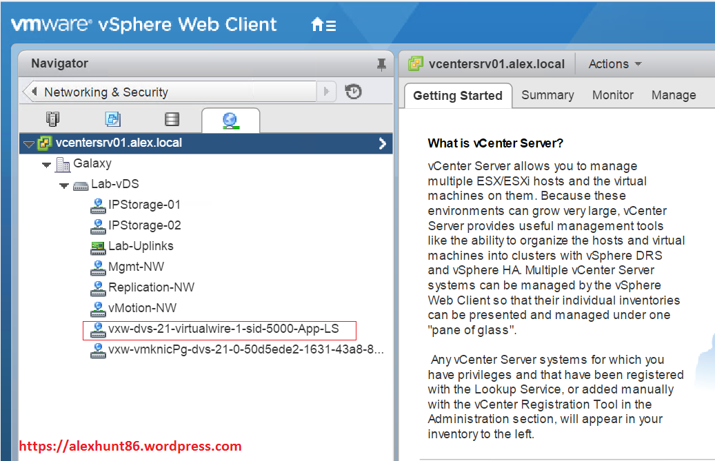
3. When you create a logical switch, a new dPortGroup is created on the vDS. You can verify this by going into your network inventory and checking the presence of the newly created portgroup.
Migrating VM’s to Logical Switch
Once logical switch is created, we can migrate the workloads onto this switch. There are 2 methods of doing this.
A: Go to Networking & Security | Logical Switches and clicking on the VM icon as shown in figure. This method will allow to migrate multiple VM’s at once from their current network (portgroup) to the logical switch.
The second method is rather long and needs going VM by VM basis and edit their settings and changed the portgroup association of the vNIC.
Select the VM’s from the list and click on the blue arrow button to add them to selection window and hit next.
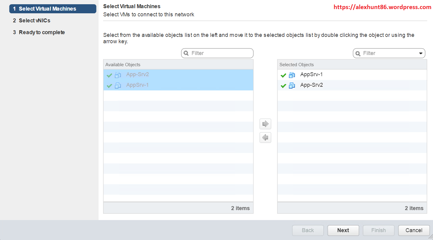
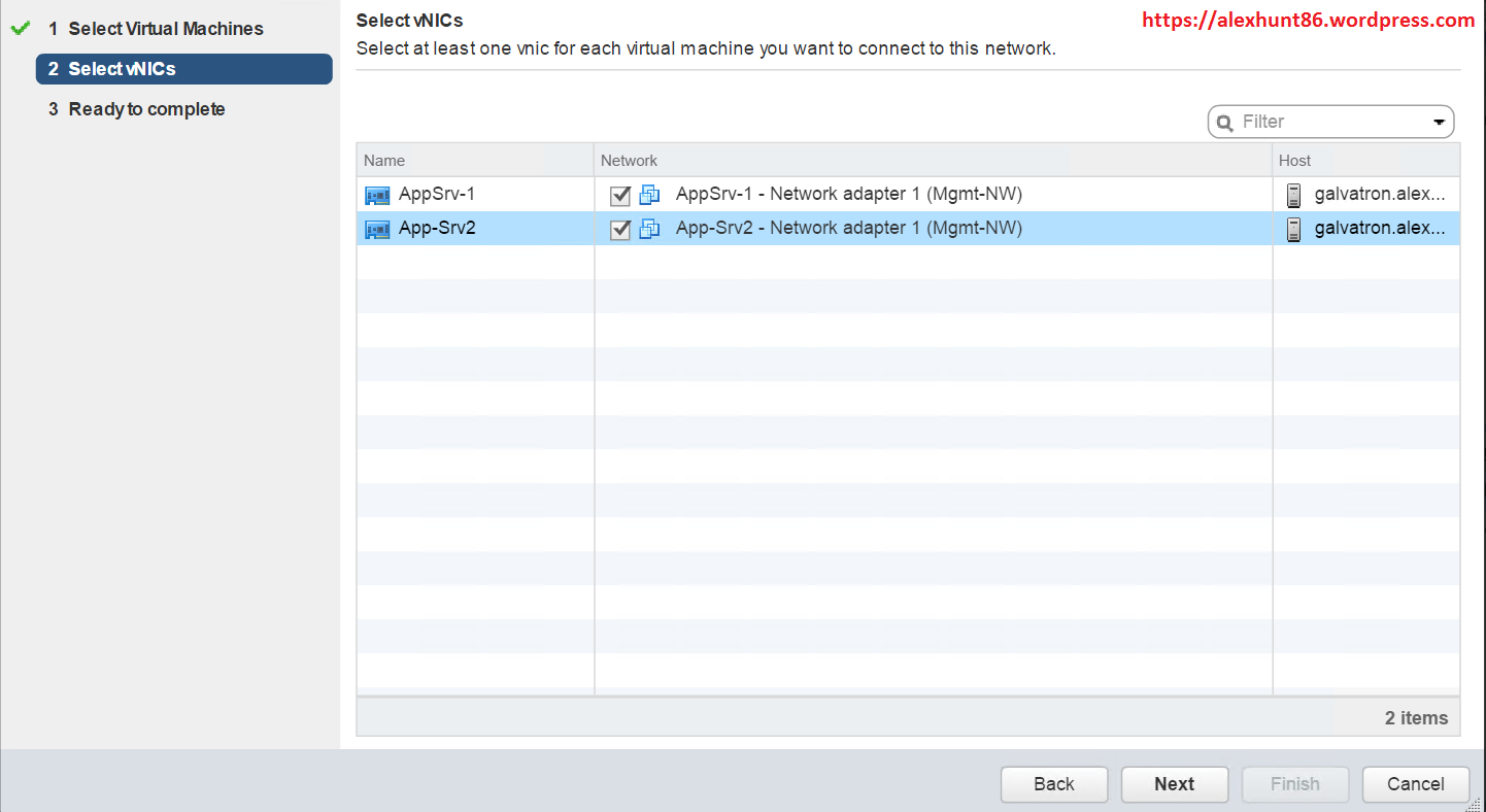
On vNIC selection page, select the vNIC’s (in case your VM has more than one vNIC) for which you want to change portgroup association and hit next. In my case all my VM was equipped with one vNIC.
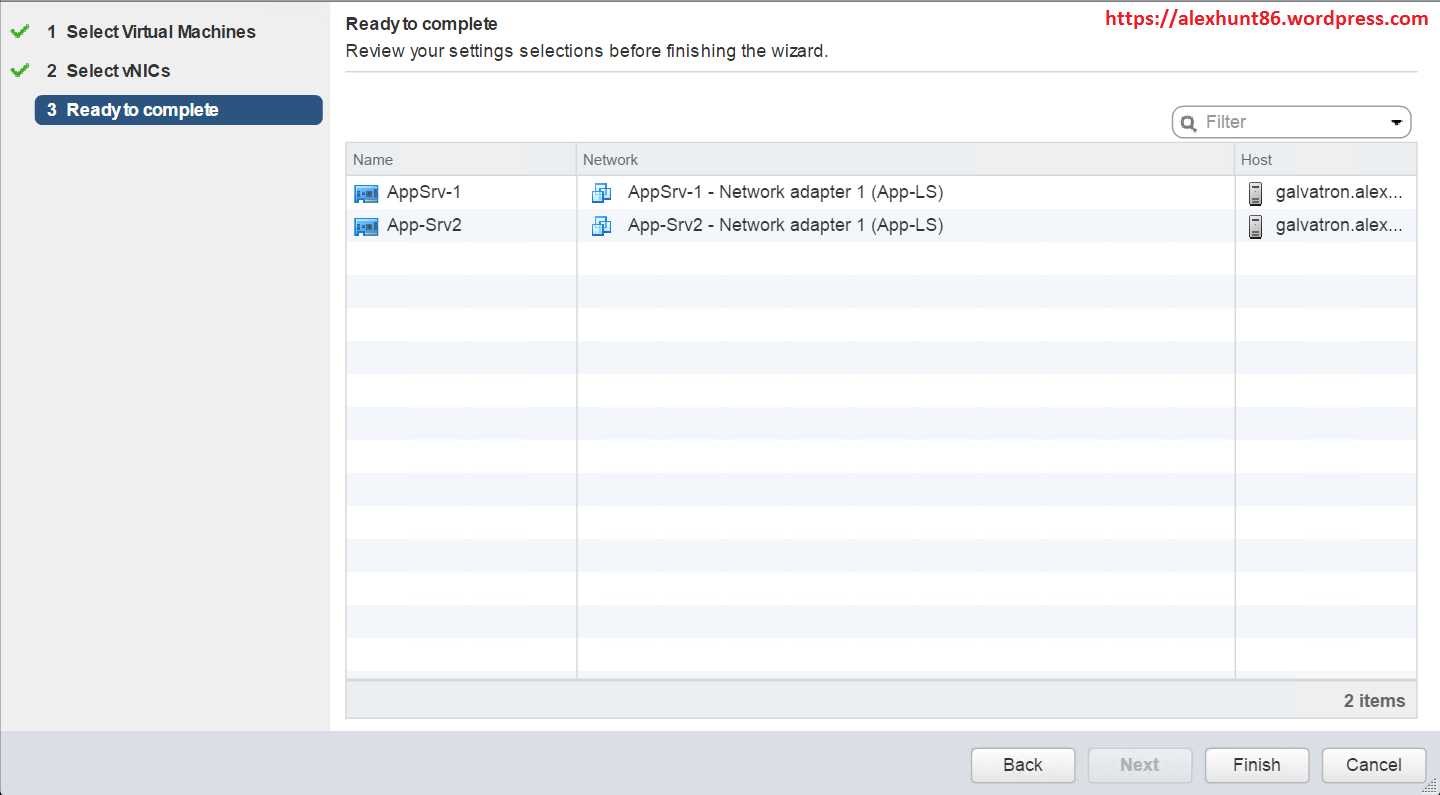
On ready to complete page review your settings and hit Finish to complete logical switch creation wizard.
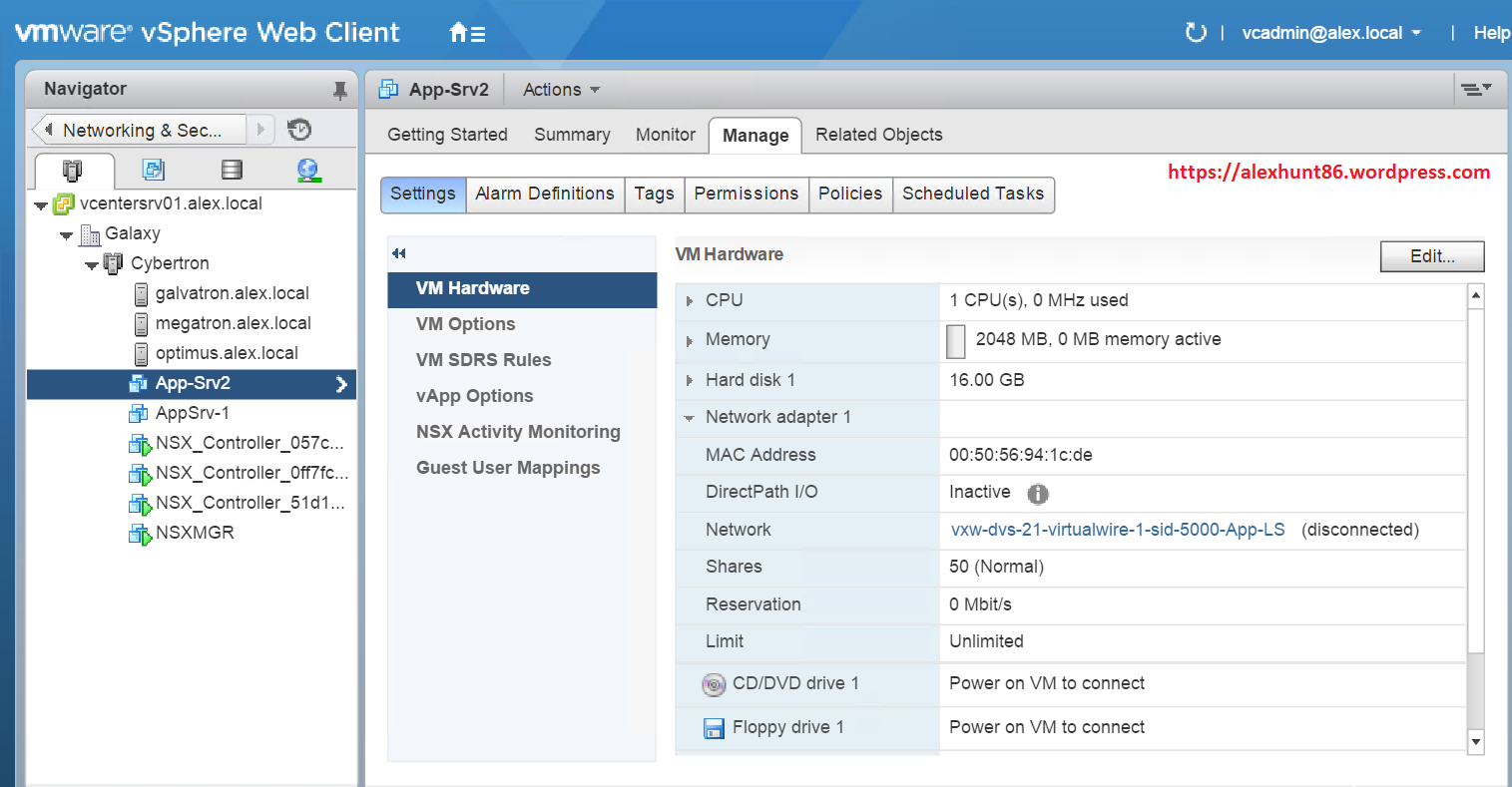
You can verify the change of portgroup association by selecting the VM and go to Manage > VM hardware tab.
So now we have created our logical switch and migrated a few VM’s on that. In next post of this series we will learn about Distributed Logical Router.
I hope you enjoyed reading this post. Feel free to share this on social media if it is worth sharing. Be sociable



7 thoughts on “Learning NSX-Part-6-Logical Switching and Transport Zones”